Electrodeionization (EDI)
Electrodeionization (EDI) is an advanced water treatment technology that produces ultra-pure water by removing dissolved ions without chemical regeneration. By utilizing ion exchange resins, selective membranes, and an electric current, EDI systems effectively eliminate impurities, ensuring high-quality water for critical applications.
EDI technology utilizes ion exchange resins and membranes to remove dissolved salts from water, driven by an electric field. This process eliminates the need for chemical regenerants, making it an environmentally friendly and cost-efficient option. With its continuous operation and low maintenance requirements, EDI systems provide reliable performance and minimize downtime.
EDI systems play a crucial role in industries such as pharmaceuticals and electronics, particularly for applications requiring high-purity water like boiler feed and ultrapure rinsing. Their reliability in meeting stringent quality standards makes them a preferred option in modern water treatment.
Electrodeionization (EDI) Product Series
Check out our product groups designed for your needs
Lab Type Electrodeionization
Electrodeionization systems designed for research laboratory applications.
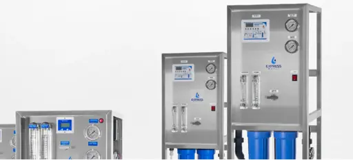

Lab Type Electrodeionization Systems

Mini Lab-Type Electrodeionization Series
Electrodeionization (EDI) systems, offering a capacity spectrum of 1 l/h to 8 l/h, are meticulously designed to generate water of exceptional purity, meeting the stringent requirements of laboratory environments.
Maxi Lab-Type Electrodeionization Series
These deionization systems, with a flow capacity ranging from 10 l/h to 50 l/h, are engineered to deliver high-purity water for lab activities with exceptional efficiency and reliability.
Industrial Electrodeinozation (EDI) Systems
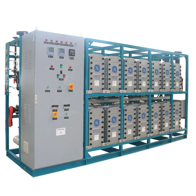
Industrial Electrodeionization (EDI) Series
Our electrodeionization (EDI) systems, with capacities ranging from 0.25 m³/h to 50 m³/h, are designed to produce ultra-pure water with a resistance of up to 20 MΩ. Compact and efficient, they can be customized as plug-and-play solutions for seamless operation.
Custom-Design Systems For Your Needs
Discover tailored custom system solutions designed to meet your specific requirements. Enhance water quality and system performance with our customizable options today!

Phone
Address
Akçaburgaz, 3026. Sk No:28, 34522 Esenyurt/İstanbul TURKEY
Electrodeionization (EDI) for Water Purification
Electrodeionization (EDI) is an advanced water purification method that produces high-purity deionized water using a combination of ion-exchange resins, ion-selective membranes, and a DC electrical field. It is typically used as a polishing step after reverse osmosis (RO), removing remaining ionic contaminants to achieve resistivities up to 15–18 MΩ·cm (ultrapure water quality). Unlike traditional mixed-bed ion exchangers that require periodic chemical regeneration with acids and bases, EDI operates continuously and without chemical reagents, as the electric field continuously regenerates the resins in-situ. This makes EDI a “green” technology, eliminating hazardous regenerant chemicals and waste, and reducing operating costs and downtime associated with resin regeneration. EDI modules are commonly referred to as CEDI (continuous electrodeionization) systems for their continuous operation. Developed in the 1980s and commercialized by the late 1980s, EDI has become a proven technology widely adopted in industries demanding high-purity water.
How EDI Works
EDI integrates principles of conventional electrodialysis and ion exchange into one process. In an EDI device, water flows through compartments filled with mixed-bed ion exchange resin that are sandwiched between cation and anion exchange membranes. A DC voltage applied across the stack causes cations to migrate toward the cathode and anions toward the anode. The ion-selective membranes direct these ions into adjacent concentrate (reject) channels, while the resin continuously exchanges ions and is electrically regenerated. Essentially, EDI involves three simultaneous phenomena:
Ion Exchange: Removal of ions from the water by ion exchange resins in the dilute (product) compartment.
Electro-migration (Electrodialysis): Separation of ions through membranes under an electric field, transporting the removed ions into concentrate compartments.
Electrochemical Regeneration: In-situ regeneration of the resin via water splitting – the electric field causes water to dissociate into H⁺ and OH⁻ which continuously recharge the resin’s exchange capacity.
By combining these stages, EDI produces purified deionized water continuously. The following sections provide a detailed explanation of each stage of the EDI process, the operating parameters to monitor, typical contaminants removed, applications, and important design, operational, and maintenance considerations for EDI systems.
EDI Process and Stages
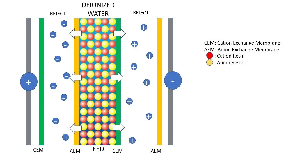
Schematic of an electrodeionization cell pair with ion-exchange resin beads (mixed cation and anion resins) between ion-selective membranes (CEM = cation exchange membrane, AEM = anion exchange membrane). An applied DC electric field (positive anode on left, negative cathode on right) drives cations (+) toward the cathode through cation-permselective membranes and anions (–) toward the anode through anion-selective membranes, into the concentrate (“reject”) chambers. This continuous ion removal yields deionized product water in the central (diluting) chamber.
EDI modules are typically constructed as stacks of many “cell pairs,” each pair consisting of a diluting compartment (also called the dilute or product chamber) and a concentrating compartment (concentrate or reject chamber) separated by ion-selective membranes. Each diluting compartment is filled with a mixed bed of cation and anion exchange resin. An anode and cathode are positioned at either end of the stack to establish the electric field. When feedwater (usually RO permeate) is introduced into the diluting chambers and a DC voltage is applied, the EDI process involves the following stages:
Ion Exchange (Deionization Stage)
In the first stage, ions in the feed water are captured by the ion exchange resins in the diluting chamber. The mixed-bed resin is initially in its regenerated form (hydrogen form cation resin and hydroxide form anion resin, similar to a fresh mixed-bed DI resin). As the water flows through the resin bed, ionic contaminants are exchanged onto the resin sites: cationic species in the water (e.g. Ca²⁺, Mg²⁺, Na⁺, K⁺, NH₄⁺) displace H⁺ ions from cation resin, and anionic species (e.g. Cl⁻, SO₄²⁻, NO₃⁻, HCO₃⁻, CO₃²⁻, F⁻, silica (SiO₂⁻), borate) displace OH⁻ ions from anion resin. The released H⁺ and OH⁻ immediately recombine to form pure H₂O. Through this ion exchange mechanism, the feed is deionized as it passes through the resin bed – effectively the resin scavenges the dissolved ions and purifies the water. This deionization by resin is analogous to a conventional mixed-bed ion exchanger, but it occurs continuously in EDI rather than batchwise. By the time water reaches the outlet of the diluting chamber, most of the strong ionic contaminants have been removed onto the resin. The resistivity of the water in the diluting compartment thus increases as ions are removed.
Parameters & Considerations – Ion Exchange Stage: The performance of this stage depends on feed water quality and resin condition. Important parameters to monitor include:
Feed Conductivity (TDS): EDI feed (usually RO permeate) should have low total dissolved solids (e.g. < 40 µS/cm, often much lower) to ensure the resin can initially capture most ions and that the EDI operates in its optimal range. Higher feed conductivity means higher ionic load, requiring more electrical current to remove ions; if excessive, the EDI resin may struggle to polish the water to high purity.
Feed Hardness: Even trace hardness (Ca²⁺, Mg²⁺) can exhaust resin exchange sites and cause scaling in the concentrate. Typically, feed hardness is limited to ~1 mg/L as CaCO₃ (often <0.1 mg/L for ultra-pure applications). Hardness is usually removed by upstream softening or by the RO. If hardness exceeds design limits, it can precipitate as CaCO₃ in the concentrate or even foul the resin, reducing ion exchange efficiency.
Feed CO₂ (Carbon Dioxide) and Weakly Ionized Species: CO₂ in water forms bicarbonate/carbonate which the anion resin will capture, consuming OH⁻. EDI feed often requires CO₂ degassing after RO if CO₂ is high, because CO₂ does not conduct but will load the resin and later be released as bicarbonate, affecting resistivity. Silica (weakly ionized H₄SiO₄) is another species – it should typically be <1–2 mg/L in EDI feed. These weak acids/bases are not fully removed by RO but can be handled by EDI’s continuous regeneration (discussed later).
Flow Rate through Resin (Residence Time): Sufficient flow residence time in the resin bed is needed for effective ion exchange. If flow is too high, the ion removal may be incomplete; too low and risk of scaling in concentrate rises. Manufacturers specify a range – for example, a module might handle 1.5–2.2 m³/h of product flow. Operating within design flow ensures the ion exchange step can occur efficiently.
Temperature: Resin exchange kinetics and conductivity improve with temperature (within limits). EDI modules typically operate between 10 °C and 38 °C. Below ~10 °C, resin ion mobility is reduced and deionization is less efficient; above the max, resin or membrane materials can degrade. Maintaining feed temperature in range keeps the ion exchange stage effective.
During normal operation, the ion exchange stage should remove the bulk of ions, and the product water conductivity drops significantly across the resin bed. If sensors show abnormal conductivity early in the process (e.g. mid-cell measurements if available, or unexpected drop in resistivity of product), it may indicate resin exhaustion or fouling at this stage. In practice, because the resin is continuously regenerated by the later stage, the ion exchange capacity is sustained – any decline in performance usually points to issues like organic fouling of resin or insufficient regeneration current, rather than simple exhaustion as in a static mixed bed system.
Ion Migration (Electrochemical Separation Stage)
The second stage of EDI is the electrochemical separation of the ions via ion migration under the applied DC electric field. Once the resins in the diluting chamber capture ions, those ions are not retained permanently – the electric field pulls them off the resin beads and drives them out of the diluting compartment. Cations desorbed from the cation resin migrate toward the negatively charged cathode, and anions from the anion resin migrate toward the positively charged anode. On each side of a diluting compartment, ion-selective membranes allow the passage of either cations or anions into the adjacent concentrating compartments:
Cation exchange membranes (CEM) border the side of the dilute chamber facing the cathode. These membranes permit cations to pass through into the concentrate chamber, but reject anions.
Anion exchange membranes (AEM) border the side facing the anode, allowing anions to migrate out, but blocking cations.
As the ions are drawn out of the diluting cell through the appropriate membrane, they enter the concentrate chambers. Importantly, a second membrane on the far side of each concentrate chamber prevents the ions from migrating further into the next diluting cell. For example, a cation that passed through a CEM into a concentrate chamber will encounter an anion membrane on the opposite side of that chamber, which it cannot pass, effectively trapping the cation in the concentrate compartment. Similarly, anions leaving a dilute cell are confined by a cation membrane on the far side of the concentrate. In this way, the removed ions are collected in the concentrate channels (which carry a slow-flowing brine stream), isolating them from the product water stream. The net result is a continuous ion removal and transfer: the diluting stream is stripped of ions and becomes deionized product, while the concentrate stream carries away the removed ions.
This stage is essentially an electrodialysis process enhanced by resin. The presence of ion-exchange resin in the diluting compartments greatly increases the conductivity and facilitates ion transport, allowing EDI to achieve much lower residual ion levels than electrodialysis alone. The resin provides a high-density pathway of charged functional groups so that even as the water becomes very pure (and its direct conductivity drops), the electrical current can still travel via the resin, pulling ions along. Without resin, once the water’s ionic content became low, the resistance would rise and limit further ion removal; with resin, a steady conductive medium remains, enabling removal of ions to trace levels.
Parameters & Considerations – Separation Stage: Key factors in this stage involve the electrical and hydraulic conditions that drive ion migration:
DC Current / Voltage: The driving force for ion migration is the electric current applied. EDI systems are often operated under a constant current (or current-limited) mode to maintain a desired removal. Sufficient current must be supplied to carry away all the ions from the diluate. If the current is too low, some ions will remain on the resin and leak into product; too high, and excess electrochemical reactions (water splitting, gas evolution) can occur (up to design limits). Manufacturers specify the optimal current range per module (e.g. a module may use ~4–9 A). For instance, a DuPont EDI module allows up to 9.0 A and ~160 V DC per module. The system’s DC power supply (rectifier) must be sized accordingly and kept stable (output current not fluctuating beyond ±5%). Typically, the voltage will adjust based on the feed water conductivity and desired current; as the feed water becomes more pure during operation, the resistance increases and the required voltage might rise. Monitoring the stack voltage at a given current can indicate if the cells are becoming fouled or scaled (a rising voltage over time at same current suggests higher resistance, possibly due to membrane scaling or resin fouling).
Flow Rates (Diluate and Concentrate): The dilute (product) flow rate influences residence time as noted, but also affects how quickly ions are swept out after exchange. Concentrate flow rate is equally crucial – it must be high enough to flush removed ions out of the concentrate chambers and prevent precipitation, but not so high as to dilute the ionic content excessively or cause undue pressure drop. Many EDI systems set the concentrate flow at about 5–10% of the product flow, resulting in a concentrate reject of ~5–10% of feed water (e.g. 90–95% water recovery). Higher recoveries are possible by recycling the concentrate back to the RO feed, but only if carefully engineered (recycling can increase CO₂ load and risk reintroducing impurities). It’s important to monitor concentrate outlet conductivity – a rising concentrate conductivity indicates it is carrying away ions (normal), but if it becomes too saturated (approaching scaling limits) or too low (indicating perhaps low ionic load or membrane leakage of product water), it may signal issues. Typically, concentrate conductivity will be higher than feed conductivity since it collects the ions.
Pressure and Leak Control: The diluting and concentrating streams are at slightly different pressures – concentrate outlet is usually maintained at a lower pressure than the dilute/product outlet to prevent any back-leakage of concentrate into product. Operators monitor pressure differential: the concentrate outlet pressure should be a few psi lower (e.g. 0.5–0.7 bar lower) than the product outlet. If pressure differential in the wrong direction occurs, product water could be contaminated by concentrate. Also, measuring pressure drop across the diluate compartments helps detect fouling (an increasing pressure drop means flow channels in resin might be plugging with debris or scale).
Membrane Health: While not a direct “parameter,” the integrity of ion-selective membranes is vital. If a membrane is damaged (tear or leak), it can cause cross-contamination of streams. Conductivity or ionic analysis of streams can sometimes detect this (e.g. unexpectedly high ions in product or odd pH shifts). Regular monitoring of product resistivity and visual inspection of concentrate for precipitates can help catch membrane issues.
During operation, the separation stage is largely self-regulating given a fixed current and flows. Operators will keep an eye on the product water resistivity continuously – this is an aggregate measure of how well the entire process is removing ions. A consistently high resistivity (low conductivity) means the migration stage is effectively clearing ions. If product resistivity starts dropping below the target (e.g. below 1 MΩ·cm or below the spec like 5 MΩ·cm for boiler feed, or 15 MΩ·cm for semiconductor grade), it suggests that ion removal via migration is insufficient, possibly due to inadequate current, foulants impeding ion transport, or exhausted resin (if regeneration isn’t keeping up). In such cases, operators may increase the current (if capacity allows), perform maintenance/cleaning, or check the feed quality to restore performance.
In-Situ Regeneration (Electrochemical Regeneration Stage)
A unique and critical aspect of EDI is the continuous electrochemical regeneration of the resin bed. This third stage occurs simultaneously as the resin removes and transports ions. As the diluting water becomes very low in ionic content toward the outlet of the resin bed, the ions available to carry electric current are depleted. However, rather than the current stopping, the strong electric field causes a portion of the water to dissociate (split) into hydrogen (H⁺) and hydroxide (OH⁻) ions. This phenomenon, essentially a localized electrolysis of water, is often termed “water splitting” in EDI. It happens predominantly at the interfaces of the resins and membranes or at resin-resin junctions when the local potential exceeds a threshold (approximately 0.8 V across a resin bead-membrane interface is sufficient to split water molecules). The newly generated H⁺ and OH⁻ ions immediately attach to the ion exchange resin, regenerating the cation resin to H⁺ form and anion resin to OH⁻ form in situ. This is equivalent to continuously recharging the resin with acid and base, but it is accomplished electrically and on a continuous basis.
The water splitting and regeneration is what enables EDI to produce ultra-pure water continuously without chemical downtime. In effect, the resin in the latter part of the diluting chamber is constantly being regenerated by the H⁺/OH⁻ produced, which displace the captured impurity ions. Those displaced impurity ions (e.g. Na⁺ on a resin site gets kicked off by H⁺) then join the migration and are swept into the concentrate. The H⁺ and OH⁻ that took their place on the resin eventually recombine to form water once the resin site moves to a fresh section, or they neutralize weak acids/bases in the water. This self-regeneration cycle means the resin bed never exhausts as in a conventional system; it is continually regenerated internally. As a result, EDI can maintain a high product water purity consistently over time, rather than the typical exhaustion curve of a stand-alone ion exchanger.
One notable benefit of this regeneration by water splitting is the removal of weakly ionized contaminants like carbon dioxide (as H₂CO₃) and silica. In a mixed-bed ion exchanger, CO₂ and SiO₂ are difficult to remove once the strong ions are depleted, but in EDI, the regenerated H⁺ and OH⁻ effectively neutralize these species: CO₂ is converted to bicarbonate/carbonate and removed by the anion resin, and silica (a weak acid) can be deprotonated by OH⁻ to form silicate which is then removed. Thus, EDI can achieve further removal of these weak contaminants after the strong ions are gone. This is why EDI is often used to “polish” RO water, as RO may not fully remove dissolved CO₂ or silica but EDI can polish them out by virtue of the high-resistivity regime and continuous regeneration.
Parameters & Considerations – Regeneration Stage: The primary driver for regeneration is maintaining an appropriate electrical current (or current density) that exceeds the “limiting current” of the dilute compartments. The limiting current is the threshold at which the available ions in the diluate are fully transported; beyond this, the additional current causes water splitting. Operators ensure that the EDI system is operated slightly in the over-limiting current regime to sustain continuous regeneration. Key points include:
Current Setpoint for Regeneration: EDI units are typically designed with a target current that both removes the ionic load and provides enough excess to split water. For example, if a feed has a certain total ionic load (often quantified as total exchangeable anions/cations in equivalents), the system design will specify a minimum current to carry those ions. Any current above that goes into regenerating the resin by water splitting. If the current is set too low (below the needed value), the resin in the later part of the cell could become saturated and not regenerate, leading to leakage of ions. If the current is too high, water splitting is excessive, which can raise product pH or concentrate pH excessively and potentially cause scaling or accelerated membrane degradation, and it wastes energy. So, controlling current within the optimal band is crucial. In practice, many EDI systems operate at a fixed current and rely on the feed quality being within spec. If feed ionic load increases (e.g. higher CO₂ or a leak of hardness), the operator may need to increase current to maintain regeneration.
Voltage Monitoring: As mentioned, an increasing voltage for a given current may indicate scaling or fouling. One particular aspect of water splitting is that it can increase the local pH in concentrate (where OH⁻ accumulates) and decrease pH in regions near the anode (where H⁺ accumulates). Extremely high current can thus lead to high pH in concentrate which might precipitate silica or calcium carbonate. Monitoring concentrate pH or calculating Langelier saturation index can be a part of controlling scaling during regeneration. Some systems limit current or recovery to keep concentrate pH below certain values (e.g. if concentrate pH goes >10 due to excess OH⁻, silica might polymerize).
Resin Condition: Over time, resins can lose capacity due to fouling or oxidative damage. The regeneration process keeps them active, but if resin is damaged (e.g. by chlorine attack or organic fouling), even water splitting won’t fully restore exchange sites. If operators notice that even at normal or maximum current the product resistivity is trending downwards over months/years, it could indicate resin attrition and reduced regeneration efficacy. That may necessitate module replacement.
Temperature Effects: Water splitting is endothermic and also limited by kinetics; warmer water can facilitate easier dissociation. Operating at too low temperature might slightly hinder the efficiency of regeneration (in addition to ion exchange). However, this is typically a minor factor compared to current control.
In summary, as long as the EDI is supplied with sufficient current relative to the ionic load, the electro-regeneration will automatically occur and keep the resin in H⁺/OH⁻ form. This stage is largely “invisible” to the operator during normal running – its success is reflected in the stable high resistivity of the product water and the long life of the resin. It eliminates the need for external chemical regeneration steps. If this stage falters (due to inadequate current or poisoned resin), it becomes evident through a drop in product water quality. In such cases, one might perform a manual regeneration assist (for instance, some operators will circulate a dilute acid/base temporarily or boost current in a recirculation mode to recondition the resin). However, under ideal conditions, the continuous electrical regeneration suffices for the life of the module.
Typical Contaminants Removed by EDI
EDI is effective at removing virtually all ionized or ionizable species from water. Typical contaminants and ions removed include:
Cationic contaminants: Calcium (Ca²⁺), Magnesium (Mg²⁺), Sodium (Na⁺), Potassium (K⁺), Ammonium (NH₄⁺), Iron (Fe²⁺/Fe³⁺), Manganese, and other metal cations are readily removed by cation exchange resin in the EDI. This includes trace heavy metals (Cu²⁺, Ni²⁺, Zn²⁺, etc.) often found in feed or in certain waste streams.
Anionic contaminants: Chloride (Cl⁻), Sulfate (SO₄²⁻), Nitrate (NO₃⁻), Bicarbonate/Carbonate (HCO₃⁻/CO₃²⁻), Fluoride (F⁻), Silicate/Silica (typically present as H₂SiO₃ or SiO₂·nH₂O), Boron (as borate anion), and others are removed by the anion resin. Even weakly dissociated acids like carbonic acid (H₂CO₃ from CO₂) and silicic acid (H₄SiO₄) are effectively eliminated because the high-pH environment from resin OH⁻ helps ionize them for removal.
Ionizable organic compounds: EDI can remove charged organic species such as organic acids (e.g. acetic acid, formic acid in their dissociated form) and low molecular weight ionizable organics. These are captured by resins if they carry charge. However, neutral organics (non-ionized) are not removed by the ion exchange mechanism except incidentally by adsorption, so EDI is not designed for organic removal beyond ionic organic matter. Total Organic Carbon (TOC) that is non-ionic should be minimized in the feed (e.g. via RO and activated carbon) to prevent fouling.
Silica: Worth special mention, silica (often reported separately in high purity water) is removed as silicate ions. EDI product water often has very low silica, meeting stringent requirements (<0.1 mg/L) for industries like power and semiconductor. Thin-cell EDI designs allow slightly higher feed silica (up to ~2 mg/L) than older designs, but still product silica is greatly reduced.
Gases and Dissolved Ionizable Gases: Dissolved CO₂ as mentioned is handled by conversion to ionic form. Ammonia (NH₃/NH₄⁺) if present (from chloramine breakdown or other source) would be captured as ammonium ion on cation resin. Oxygen or nitrogen gases are non-ionized and pass through (though not typically a concern for purity, more for corrosion which is handled elsewhere). EDI does produce H₂ and O₂ gases at the electrodes (which are vented, not in product water).
In essence, any ionic impurity – whether a salt, mineral, or inorganic contaminant – can be removed by EDI. After RO pre-treatment, the typical remaining ions might be on the order of a few mg/L or less; EDI will polish these down to µg/L levels. For example, if RO permeate has 5–10 µS/cm conductivity (~2–5 ppm TDS), EDI can reduce that to <0.1 µS/cm (ultrapure). Common residual ions that EDI targets include sodium, chloride, sulfate, silica, and bicarbonate (from CO₂) – these are often the ions that RO leaves in low quantities, and EDI is used to remove them to meet ultrapure specs.
It should be noted that EDI does not remove microorganisms or particles (those are typically filtered/UV-treated upstream). Also, EDI has no specific mechanism to remove completely non-ionic contaminants (e.g. dissolved organics like benzene, or very weak acids/bases that remain un-ionized); such contaminants must be addressed by other purification steps if required. But for ionic contamination, EDI provides an extremely effective polishing, often achieving ion removal to detection limits.
Applications of EDI in Industries
EDI systems are employed across numerous industries where high-purity or deionized water is required. Key application areas include:
Semiconductor and Microelectronics: The electronics industry requires ultrapure water (UPW) for rinsing and cleaning semiconductor wafers and components. Even trace ionic contaminants can cause electrical shorts or defects on microcircuits. EDI is widely used in semiconductor fabs as part of multi-step water purification (typically after RO and ultrafiltration) to achieve resistivity ~18 MΩ·cm. By removing ions continuously, EDI ensures the rinse water leaves no conductive residues on chips, preventing short-circuits in densely packed circuitry. This application often demands the highest water quality; EDI helps achieve extremely low silica and boron levels, which are critical in semiconductor water specs.
Pharmaceutical and Biotechnology: Pharmaceutical manufacturing and biotech labs use deionized water for preparing formulations, cleaning equipment, and as ingredient water (e.g. for parenteral solutions, media preparation). Ionic impurities can catalyze undesirable reactions or cause precipitates in drug solutions. EDI, in combination with RO and UV, is commonly used to produce USP Purified Water and even as part of generating Water-For-Injection (WFI) (though WFI may require distillation or ultrafiltration as final step). Because EDI has no chemical regenerants, it avoids introducing any chemical additives and maintains consistent water quality, which is important for validation in pharma. The continuous operation also means no downtime for regeneration, ensuring a reliable supply of high purity water for critical processes. Pharmaceutical installations value the fact that EDI modules do not foster microbial growth easily – the high purity, high resistivity environment and constant electric field create a biostatic condition that inhibits microorganisms.
Power Generation (Boiler Feed Water): The power industry requires demineralized water for steam generation in boilers and for makeup water in high-pressure steam turbines. Any ionic impurities in boiler feed can lead to scale deposits on turbine blades or boiler tubes and lead to corrosion and efficiency loss. EDI systems polish RO permeate to provide demineralized water with extremely low conductivity and silica, protecting boilers from scaling and preventing buildup of conductive deposits that could cause hot spots or corrosion. In the power sector, EDI often replaces or augments traditional ion exchange demineralizers, eliminating the acid/caustic handling on site. The reliable continuous production helps power plants maintain steady operation – as impurities in the steam cycle are minimized, turbines and heat exchangers run longer between cleanings. EDI units for power plants are typically designed for large flow rates and often integrated into skid-mounted demineralization trains including pre-filters, RO, and EDI.
Food and Beverage: Many food & beverage operations use deionized water for product dilution, ingredient water, or utility purposes (like boiler feed for steam in direct contact with products). For example, bottled beverage production may use EDI-polished water to ensure taste neutrality and stability (ions like calcium or sulfate could affect flavor or interact with product formulations). Breweries and dairies may use demineralized water to blend to desired mineral content. EDI provides a consistent water quality without risk of resin regenerant contamination. In sweetener or ingredient manufacturing, deionized water produced by EDI can improve product purity. Additionally, the absence of regeneration chemicals is a benefit as it avoids any potential for chemical residues in food-grade applications. (Note: EDI product water in food/bev is usually remineralized or blended to some extent for taste or nutrition, but EDI ensures a known starting purity).
Laboratory and Analytical Water: Laboratories (chemical, biological, analytical labs) often require Type I and Type II reagent grade water for experiments and instrument feed (e.g. for HPLC, GC, cell culture, etc.). EDI modules are frequently incorporated into lab water purification systems (after RO) to continuously produce 18 MΩ·cm ultrapure water for critical analytical applications. Because EDI can run continuously, lab systems can recirculate water through EDI to maintain purity in a storage loop. It also reduces cartridge replacements – EDI essentially acts as a continuous mixed bed polisher that doesn’t exhaust quickly, cutting down the cost and maintenance of lab water systems. Many commercial lab water units (for example, those by Millipore or Thermo) use small-scale EDI modules in combination with other polishing steps (UV, 0.2 µm filter) to achieve required purity for sensitive analyses.
Environmental and Wastewater Treatment: Beyond pure-water production, EDI has been applied to treat certain wastewaters, especially for removal and recovery of heavy metals or other ionic pollutants. For instance, in electroplating or metal-finishing wastewater, EDI can remove metals like chromium (Cr³⁺/Cr⁶⁺), copper (Cu²⁺), cobalt, nickel, etc., concentrating them in a reject stream for recovery or proper disposal. In nuclear wastewater management, EDI has been studied for removing radionuclides such as cesium (Cs⁺). EDI in these applications can achieve high ion removal efficiency; however, feed conditions are more challenging (higher TDS, presence of competing ions). Often specialized EDI setups or multi-stage EDI are used for such purposes. The advantage is that EDI doesn’t produce a large volume of spent chemical regenerant; instead, it yields a smaller concentrated brine with the contaminants, which can simplify downstream handling of hazardous wastes. In environmental applications, EDI is valued for its ability to operate continuously and its potential for selective removal (by adjusting membrane/resin types) for specific ions.
The above are major uses, but there are other niche applications as well (such as in the chemical industry where deionized water is used for dilutions and cleaning, or in automotive for battery water production, etc.). In summary, any process that requires a reliable supply of high-purity or ultrapure water, free of dissolved salts, is a candidate for EDI technology. The widespread adoption in electronics, pharma, and power sectors is driven by the critical need for consistent water quality and the economic/environmental advantages of eliminating chemical regeneration.
Operational Considerations for Performance and Longevity
Operating an EDI system requires attention to certain water quality parameters and system conditions to ensure optimal performance and extend the life of the modules. The following are key operational considerations and what should be monitored during EDI operation:
Feed Water Quality Monitoring: As emphasized, the feed to EDI must be pre-treated (usually by RO and possibly degassing/softening) to meet specific quality criteria. Operators should continuously or regularly monitor feed conductivity, hardness, silica, and CO₂ levels, and presence of oxidants. Conductivity gives a quick indication of total ionic load, but it may not reveal weakly ionized species (CO₂, SiO₂); hence measuring Total Exchangeable Anions (TEA) or calculating CO₂ based on alkalinity/pH is useful. Hardness should be measured – even slight upsets in a softener or RO bypass could raise hardness and risk scaling. If hardness creeps above spec (>0.1–0.2 ppm as CaCO₃), operators may need to reduce EDI recovery or perform a preventive scale cleaning. Silica in feed should be monitored if the upstream RO is not double-pass (some sites also include an ion exchange or adsorbent step for silica if RO rejection is insufficient). CO₂ is monitored via feed alkalinity or a CO₂ sensor; high CO₂ can be removed by a degassing membrane or forced draft degasifier before EDI to reduce load on the anion resin. Oxidizing agents (chlorine, chloramine, ozone) must be undetectable in the feed – typically <0.02 ppm free chlorine – as these will attack ion exchange resins and membranes, irreversibly damaging them. Online ORP or chlorine monitors are often used after activated carbon or sodium bisulfite dosing (common methods to dechlorinate feed) to ensure no oxidant breakthrough. Feedwater SDI (silt density index) or turbidity is also considered; although RO should handle particulates, any colloidal fouling that escapes into EDI can clog the resin bed. EDI feed turbidity is typically kept <0.1 NTU.
Product Water Quality Monitoring: The primary product parameter is resistivity (or conductivity). High resistivity (in MΩ·cm) is the goal; any drop in resistivity indicates a performance issue. Online resistivity meters (temperature-compensated to 25 °C) are used at EDI outlets – for example, a continuous reading of >15 MΩ·cm might be required by a process, with alarms if it falls below that. Sudden decreases in resistivity could mean a spike in feed contaminants, exhaustion of resin (if current insufficient), or a failure like a torn membrane allowing leakage. By tracking resistivity trends, operators can detect gradual fouling or step-changes. In critical applications, silica levels in product are also measured (e.g. by online silica analyzers in power plants) since silica breakthrough can occur before general conductivity rises (silica is weakly conductive). Additionally, product pH is sometimes monitored; EDI product water is often slightly elevated in pH (7–9) because of trace OH⁻ leakage, but a drastic pH shift could indicate imbalance in cation/anion removal (for instance, if anion resin is exhausted, CO₂ might pass through and lower pH).
Concentrate Stream Monitoring: The concentrate (reject) flow carries away impurities, and its condition can affect EDI longevity. Operators ensure the concentrate flow rate is within design and often monitor concentrate conductivity and pH. A very high concentrate conductivity could mean an excessive ion load or inadequate flushing (risking precipitation of salts in the concentrate chambers). Concentrate pH trending high (due to OH⁻ accumulation from water splitting) can foreshadow scaling (CaCO₃ or Mg(OH)₂ or SiO₂ if those ions are present). Some systems bleed a small portion of concentrate or dose acid to control pH if needed. Also, concentrate outlet pressure is monitored to maintain that slight negative differential relative to diluate as mentioned; if a concentrate flow is blocked or valve mis-set causing high pressure, it could force concentrate back into product side – a condition to avoid.
Flow Balance and Recovery: During operation, the ratio of diluate (product) flow to concentrate flow is maintained per spec. If product flow is increased, concentrate flow or recirculation might need adjustment to keep recovery in range. Most systems have rotameters or flow sensors on product, concentrate, and electrode rinse streams – these should be checked regularly. A low-flow alarm on product water is usually installed to prevent running the module with insufficient flow (which can lead to localized heating and resin degradation). In fact, EDI modules are often protected by interlocks: a minimum flow switch on the product (dilute) line to shut off the DC current if flow is too low, and pressure reliefs to avoid overpressure. Operators should verify these safety controls are functional. Maintaining the recommended flow distribution (e.g. product vs concentrate vs electrode flush) is important. Any prolonged imbalance (like no flow in electrode rinse) can cause scaling or drying in parts of the module.
Electrical Parameters: The DC power supply’s output current and voltage should be monitored continuously. Many EDI systems have an ampere display and often operate at a set current. The current draw will reflect how much ionic load is being processed – if feed water quality worsens, the module may demand more current (if run in constant-voltage mode) or the product quality will drop (if current-limited). Typically, systems are operated in constant current mode: the current is fixed at a value above the theoretical minimum for the feed TDS. The voltage will then float to whatever is needed, up to a maximum. Operators keep an eye on the voltage: if it climbs near the power supply limit, that might indicate the cells are becoming less conductive (potential fouling). A sudden drop in required voltage could indicate a leak or shortcut (loss of resistive path). Some systems incorporate both current and voltage alarms. It’s also good practice to record the current efficiency (ratio of ionic removal equivalent to current passed) periodically as a diagnostic of performance. Over time, if scaling occurs, the fraction of current going into useful ion removal might decrease (more goes into water splitting), which can be inferred from changes in concentrate conductivity vs current.
Preventing Fouling and Scaling: To ensure longevity, operators strive to keep the EDI clean. Pre-treatment maintenance is key – e.g. ensuring RO membranes are working and not passing excessive hardness or organics. Upstream cartridge filters should be replaced on schedule to avoid particulates fouling resin. If there is a risk of organic fouling (e.g. feed has high TOC or biological content), adding a UV lamp before EDI (to oxidize organic compounds) or performing periodic sanitizations can help. Some facilities periodically recirculate a cold sanitizing solution (like dilute NaOH or a specialized biocide) through the EDI to prevent biofilm, although the need is reduced since the electric field and high purity conditions are not favorable for microbes.
Continuous Logging: Modern EDI skids have instrumentation to log pressures, flows, resistivity, temperatures, etc. Regular review of these logs can reveal subtle trends – for example, a slowly decreasing product resistivity over weeks could signal fouling, which the operator can address before it hits alarm levels. Logging also helps in troubleshooting if an excursion occurs.
In summary, the operator should treat an EDI much like an RO or other critical water unit – maintain stable operating conditions, keep the feed within specification, and respond to any alarm or drift in parameters promptly. By doing so, the EDI will consistently produce high-quality water and the modules will last their expected lifespan. Many systems can run for years with minimal intervention aside from routine monitoring, especially if pretreatment is robust.
Design and Installation Considerations for EDI Systems
When planning to install an EDI system, several technical factors must be considered to ensure successful integration and operation:
Pre-Treatment Requirements: EDI is not a stand-alone purifying step; it relies on upstream treatment to reduce the load. Reverse osmosis is virtually always required before EDI, as it brings TDS down by 90–99%, providing a suitable feed. Additionally, upstream softening (ion exchange or antiscalant dosing) may be needed to protect the RO (and hence the EDI) from hardness. A degassing unit (membrane degasser or decarbonator) to strip CO₂ from RO permeate is often included to reduce the ionic load on EDI (by preventing bicarbonate formation). Activated carbon filters or chemical dechlorination are mandatory to remove chlorine/oxidants pre-RO so that none reach the EDI. Essentially, ensure the feed meets all the quality specs recommended by the EDI manufacturer (conductivity, SDI, hardness, silica, TOC, chlorine, etc.) at all times. If the source water quality is variable, robust pretreatment systems and possibly redundancy should be in place; EDI is sensitive to excursions beyond its design envelope.
System Sizing and Module Configuration: Determine the required product flow rate and choose the number and size of EDI modules accordingly. EDI modules come in various capacities – for example, some modules produce ~2 m³/h each, so larger flow systems will use multiple modules in parallel. Modules can also be staged in series for extra high purity (less common, as one module usually suffices after RO). The system design should allocate space for the EDI skid, including the DC power supply (rectifier) and control panel. The DC rectifier must be sized to supply the total current for all modules at the necessary voltage. If 4 modules at up to 9 A each are used, the supply should handle ~36 A at the expected voltage (which could be 100–300 VDC depending on module design). It is wise to have some overhead in the power supply capacity. Proper electrical design including grounding is critical – all piping and modules should be grounded since the water and equipment are at high voltage relative to ground during operation. Safety interlocks (door switches on electrical panels, etc.) and following electrical codes is mandatory for operator safety.
Hydraulic Integration: The EDI modules typically are skid-mounted with manifolds for feed, product, and concentrate. The feed pump for EDI (often the RO high pressure pump is used with a throttle, or a booster pump is added) must deliver the required flow and pressure. Ensure the feed pump can maintain the needed flow at around 40–80 psi (typical operating pressure) to push through the EDI modules’ flow resistance. A flow control valve or flowmeter on the product line is used to set the product flow. The concentrate line usually has a flow or restrictor to set the ratio. Plan for a means to dispose of or reuse the concentrate stream – e.g. a drain with an air gap (since concentrate might contain a small amount of hydrogen gas and impurities), or piping to send it to the RO feed tank for recycle (with appropriate controls). If recycling concentrate, consider that it will reintroduce whatever CO₂ or silica it contains back to RO feed, possibly requiring adjustments in RO recovery or a degasser on the recycle loop. Additionally, the concentrate and electrode streams may need venting of gases produced at the electrodes (H₂, O₂). During installation, vent ports or degas separators are often installed on the concentrate return line to safely vent hydrogen gas and avoid accumulation (as per safety guidelines, H₂ should stay below 25% of its lower explosive limit in any enclosed space).
Materials Compatibility: Ensure all materials in contact with water in the EDI loop are compatible and won’t leach ions. Typically, piping is UPVC, polypropylene, or stainless steel. Avoid brass, copper, or any materials that could add ions. Also avoid materials that shed organics. The EDI module materials (resin, membranes, housing) are chosen by the manufacturer for purity; just ensure gaskets, adhesives in the rest of the system are similarly clean. If the application is pharmaceutical, materials may need to be FDA compliant or validated for trace leachables.
Environment and Installation Location: EDI units must be located indoors, protected from temperature extremes and sunlight. The ambient temperature should stay within the module’s operating range (10–38 °C), and ideally in a controlled room to keep water temperature stable. Freezing conditions will destroy the module (water expansion), so if there’s any risk, heat tracing or indoor installation is a must. Likewise, high humidity environments should be avoided to protect the electrical equipment (max 90% humidity per some specs). Vibration should be minimized; the skid should be on a stable floor as excessive vibration could loosen connections or harm the resin packing. Space should be allocated for maintenance access – e.g. room to disconnect and replace modules when needed, and for chemical cleaning equipment hookups.
Instrumentation and Controls: A well-designed EDI system will include instrumentation for all critical parameters. At minimum, install sensors for: feed conductivity, product resistivity, product flow, concentrate flow, feed and outlet pressures, and temperature. Often, optional sensors for feed pH, product silica, etc., are included if the process demands tight control. Interlocks should tie the EDI to the upstream RO – typically the EDI only runs when RO permeate is in spec and flowing; if RO is off or water quality is bad (e.g. high conductivity), the EDI skid can be bypassed or shut down to protect it. Include a bypass line to divert water around EDI during startup or maintenance, so you can still supply water (though lower purity) to users if needed. Control systems (PLC/HMI) can integrate EDI monitoring and alarms into the overall water plant control. Alarms for high product conductivity, low flow, high pressure, etc., should be set up to alert operators or shut off the module power before damage occurs. In power plant or continuous manufacturing, these alarms might be tied into the plant DCS.
Commissioning and Initial Start-Up: Upon installation, initial commissioning involves flushing the system with RO permeate, checking for leaks, and then powering the EDI modules. Often, a new EDI module may take some time (several hours up to a day) to reach peak purity output, because the resin might need to be fully converted to H⁺/OH⁻ form by the electrical regeneration. During first start, manufacturers may recommend circulating water in a loop and applying a high current for a few hours (electro-regeneration period) before taking product water to use. For example, an initial regeneration of 8–24 hours may be needed for a new module to achieve 16+ MΩ·cm quality. Planning this commissioning step is important so that production schedules account for it. After that, water can be sent forward (usually after verifying quality by lab testing).
Considering all these factors in the design/install phase will set the stage for reliable EDI operation. It is critical to follow the supplier’s guidelines on feed water limits, plumbing, and electrical hookup. Each EDI module model will have a detailed manual specifying these requirements, and adhering to them (e.g. pre-filter ratings, pump sizing, electrical wiring practices) ensures the system performs as intended and that warranties remain valid.
Maintenance, Troubleshooting, and Module Lifespan
One of the advantages of EDI is the reduction in routine maintenance compared to chemically regenerated ion exchangers. However, EDI systems still require careful maintenance and occasional intervention to sustain performance over years of operation. Below are maintenance procedures, troubleshooting tips, and expectations for module lifespan:
Routine Monitoring and Preventive Maintenance
As discussed in operational considerations, continuously monitor quality and system parameters. Keep logs and look for trends. Daily/Shift checks might include recording product resistivity, feed conductivity, flows, pressures, and current/voltage. Ensure no alarms or deviations. Regularly verify the function of instruments (calibrate conductivity/resistivity meters, etc., on schedule). Also, inspect the concentrate reject visually – look for any signs of precipitation (cloudiness or scale in reject flow or at the reject nozzle) and check the concentrate tubing or orifices for clogging. If a separate electrode rinse stream is used, check its flow and that its outlet is not blocked (electrode rinse often goes to drain or back to feed tank; if blocked, gas buildup can occur). In normal operation, EDI modules are somewhat self-cleaning of minor impurities (due to the continuous ion flushing), but preventive maintenance focuses on keeping feed in spec – e.g., replace prefilters (5 micron or 1 micron filters) on a regular basis, service RO as needed (cleanings, membrane replacement) to protect downstream EDI.
Cleaning Procedures
Over time, performance issues such as a gradual decline in product resistivity or an increase in pressure drop may indicate fouling or scaling that requires cleaning the EDI modules. EDI systems can be cleaned by circulating appropriate cleaning chemicals through the dilute and concentrate chambers (similar to CIP – Clean-In-Place). The choice of cleaning solution depends on the foulant type:
Scaling (mineral deposits like calcium carbonate or metal hydroxides)
The recommended cleaning is typically a dilute acid. For example, ~2% hydrochloric acid (HCl) or citric acid can dissolve Ca/Mg scale. Acid cleaning will convert the resin temporarily to the salt forms, but that is restored during re-operation.
Organic or Biological fouling, Silica deposits
A basic (high pH) cleaning is used. A dilute caustic soda (NaOH) solution around 1% is often effective to remove organic matter or biofilm and to help dissolve silica deposits. Caustic will elute organic acids from resin and hydrolyze biofilms. Sometimes a combination cleaning is done (caustic followed by acid) if mixed foulants are suspected, but one must thoroughly rinse between chemicals to avoid reaction (e.g. acid + base mixing).
Physical flushing
In addition to chemicals, a high-flow flush with deionized water can help dislodge loosely trapped particles or resin fines (if any). Ensure the velocities do not damage the resin bed, but a temporary increase in flow can be used during cleaning to carry out debris.
Cleaning is usually performed with the DC power off (no current), to avoid any electrochemical reactions with the cleaning chemicals. The procedure is to recirculate the cleaning solution through the modules (often both dilute and concentrate sides simultaneously) for a prescribed time (e.g. 30–60 minutes), then flush thoroughly with high-purity water. It’s critical to rinse out all cleaning agents, as residual acid or caustic could harm the resin or membranes if the power is turned on. After rinsing, the modules usually need to be “regenerated” electrically again – i.e. run the EDI at normal or slightly elevated current with fresh RO water in a loop until the product quality returns to spec. Operators verify post-cleaning performance by checking that product resistivity and other parameters match or improve upon pre-cleaning values. All cleaning events should be documented in maintenance logs, noting the cause (e.g. pressure drop increase, conductivity increase) and results, as this helps optimize future maintenance scheduling.
Troubleshooting Common Issues
Reduced Product Quality (Low Resistivity)
This is the most common issue that triggers troubleshooting. If resistivity falls, first check the feed water – has conductivity or CO₂ suddenly increased? If so, address the feed (RO issues, etc.). Check that the DC current is at setpoint; a power supply fault or operator error might have current too low. Also examine the concentrate flow – if concentrate or electrode rinse flows stopped (e.g. due to a pump or valve issue), the module may have accumulated ions. The solution would be to restore flows and possibly recirculate for a while to recover. If feed and flows are fine, the issue could be fouling: for instance, organic fouling on resin will reduce exchange efficiency. In that case, plan a cleaning (typically a caustic cleaning for organics). After cleaning, re-test quality. If the quality still doesn’t improve, it may indicate irreversible damage (like resin oxidation or poisoning). At that point, module replacement might be necessary.
Increased Pressure Drop
If pressure across the EDI module rises significantly, it indicates plugging in flow channels (resin or spacers). Likely culprits: particulate fouling or scaling. Check feed SDI/filter status. If scaling (e.g. CaCO₃) is suspected, an acid cleaning is warranted. If particulate, sometimes a simple high-flow flush can push out debris. Make sure no valves are partially closed. Persistent high differential pressure can compress the resin bed and further impair performance, so it should be resolved promptly. In extreme cases, the module might need to be taken apart (if possible) or replaced if a channel is permanently blocked. Prevention via proper prefiltration is key, as noted by manufacturer warnings that EDI resin interstices can plug and hurt performance quickly if exposed to particles.
Electrical Anomalies (High Voltage or Trips)
If the system’s voltage suddenly spikes beyond normal at the set current, it suggests the stack resistance increased – likely due to scaling on membranes or resin dehydration. A scale layer on a membrane will impede ion flow and raise resistance; the fix is chemical cleaning (appropriate acid or base depending on the scale). Resin drying (for instance, if an EDI was inadvertently run without water flow for a period or stored improperly) can cause loss of contact; the only fix for dried resin is usually replacement, as cracks and air pockets form. If the power supply is tripping, check for any grounding issues or shorts – a common cause is water leakage into the electrical connectors or a broken membrane causing direct electrode short-circuit. That requires physical inspection and possibly module repair or replacement.
Leakage of Resin Beads
Although rare in normal operation, if a seal in the module fails, you might see resin beads in the piping or filters downstream. This would necessitate taking the module offline and repairing or replacing it, as internal component failure has occurred.
Product Water pH Off-Spec
If product pH drifts far from neutral in an unusual way, it could indicate an imbalance (e.g. only cation removal happening but anion removal not, or vice versa). This might happen if one type of membrane is damaged or one type of resin is fouled. For example, if anion resin is fouled, silica or CO₂ could pass through, lowering pH. The resolution would target that specific fouling (caustic cleaning for organics that often foul anion resin).
In troubleshooting, a systematic approach is best: verify feed quality, then module operating conditions (flows, current, etc.), then consider performing a cleaning, and if that fails, isolate the problem to a particular module (in multi-module systems) by testing modules individually. Many EDI systems have multiple modules; by comparing performance of each (if individual measurements are available), one can identify if a single module is problematic and perhaps swap it out as a last resort.
Module Lifespan Expectations
With proper care, EDI modules have a long service life. There are installations running the same modules for 5–10 years or more without replacement. A typical expected life is often quoted as greater than 5 years of continuous operation, assuming feedwater is consistently within specifications and regular maintenance is performed. In some cases, modules can last well beyond this (“many years”) before resin or membrane degradation necessitates replacement. The factors that typically end the life of an EDI module are: irreversible fouling (from organics, silica, etc.), resin oxidation (from a chlorine incident or years of trace exposure, causing loss of capacity), or physical degradation (membrane aging, seal leaks). If the product water quality can no longer be maintained even after thorough cleaning and reconditioning, it’s a sign the module should be replaced. To maximize lifespan: maintain excellent pretreatment (no oxidants, low TOC, etc.), do not shock the module with sudden flow or power changes, avoid unnecessary shutdowns (keep it running at low load if possible rather than stopping frequently), and always keep the module wet. Never allow an EDI module to dry out during storage or shutdown, as that can permanently damage the resin and membranes. If an EDI must be taken offline for an extended time, it should be stored according to manufacturer instructions – usually kept full of water (or a preservative solution) and sealed. Some recommend periodic recirculation or powering the module briefly during long idle periods to maintain the resin in regenerated form. Manufacturers often state modules can be stored for months in a wet state; for example, DuPont specifies modules can be stored up to six months in original packaging with proper measures.
In the event a module does reach end-of-life, replacement involves depressurizing and isolating the module, disconnecting electrical and plumbing connections, and installing a new module. The new module will require the normal startup procedure (flush and initial regeneration period). It’s good practice to keep a spare module (or at least critical spares like a spare power supply, extra gaskets) on hand for systems where downtime would be critical. However, with good operation, actual module replacements should be infrequent.
In summary, maintenance of EDI is focused on preventing issues via consistent operation and pretreatment and addressing fouling early if it arises. Compared to ion exchange tanks that need frequent chemical regen or resin replacement, EDI offers a more hands-off operation. But it is by no means maintenance-free – water treatment professionals must keep an eye on it and perform periodic cleanings and checks. When properly maintained, EDI modules operate reliably, and the system can run continuously with minimal intervention, producing a steady stream of high purity water.
EDI Module Design Features and Technical Specifications
EDI modules from various manufacturers may differ in construction details, but they share common design elements. Understanding the general design and typical specs helps in evaluating and comparing EDI systems:
Construction and Materials
Most EDI modules are designed in a plate-and-frame or stack configuration, with alternating dilute and concentrate compartments separated by ion exchange membranes and filled with resin. Typical materials include PVC or polypropylene frames, ion-exchange membranes made of sheet polymers with immobilized sulfonic (cation) or quaternary ammonium (anion) groups, and mixed-bed ion exchange resin (strong acid cation, strong base anion resins in bead form). End plates hold the stack together, and electrodes (often made of inert materials like coated titanium or stainless steel) are located at the ends. Some designs, such as certain cylindrical EDI modules (e.g. from DuPont), use a spiral wound flow path for the concentrate within a cylinder, but still internally consist of stacked membranes and resin-filled compartments. All wetted materials are chosen for high purity and compatibility; for example, resins are highly regenerated and rinsed to be low TOC, membranes are similar to those used in electrodialysis (with long life and resistance to biofouling).
Mixed-Bed Resin
Inside each dilute chamber, mixed ion exchange resin is filled tightly. The resin typically has a specific ratio of cation to anion resin (often 40:60 or 50:50 by volume) optimized for conductivity and water splitting. The resin beads provide the primary deionization action and also a path for electrical current (since the water alone would be too resistive when deionized. The resin bed also helps prevent water splitting until needed by providing sample ionic conductivity in the front part of the cell, and then facilitating water splitting in the latter part by creating localized high field zones. Resin bead size and type can affect performance (finer resin can give more exchange sites but causes higher pressure drop; most use uniform fine mesh resin for performance balance).
Ion Exchange Membranes
Each cell is bordered by a cation exchange membrane (CEM) on the side facing the cathode and an anion exchange membrane (AEM) on the side facing the anode. These membranes are typically thin sheets (0.1–0.5 mm thick) that allow selective passage of counter-ions. The membranes prevent co-ion leakage, ensuring ions removed from diluate stay in concentrate. The quality of membranes (selectivity and resistance) influences the stack efficiency – high selectivity is needed so that essentially no product water ions diffuse back. Membranes are usually stable polymers like polystyrene-divinylbenzene with functional groups (–SO₃⁻ for CEM, –NR₃⁺ for AEM). They are often reinforced with fabric for strength. Membrane spacing is maintained by gaskets or spacers which also define the flow channels.
Flow Distribution
Within each chamber, there may be spacers or mesh to create turbulence and even flow distribution. Some designs use resin alone to fill the space (resin acts as the spacer), others incorporate a mesh or screen that holds resin in place and guides flow. “All-filled” designs refer to both diluting and concentrating compartments filled with resin. Filling the concentrate chambers with resin (instead of leaving them as open flow) can improve conductivity and reduce scaling by exchanging ions in concentrate as well. Many modern EDI modules adopt all-filled designs for better efficiency.
Electrical Configuration
Modules have two electrodes: the anode (positive, usually at the feed inlet end or a designated end) and the cathode (negative, at the opposite end). They connect to a DC power source. The current path goes from anode, through the concentrate/diluate compartments (via ions and resin), to the cathode. Most modules treat the electrode compartments as separate from the main flow: the electrode chambers may be fed with a small stream of the same water (often called electrode rinse or electrolyte flush) to carry away the products of electrode reactions (H₂ gas at cathode, O₂ and possibly Cl₂ gas at anode if any chloride is present). This electrode rinse stream is usually a portion of concentrate or a separate feed; it exits as waste. In terms of wiring, multiple modules can be wired in parallel to the same power supply (each seeing the same voltage), or sometimes in series for higher voltage distribution – but parallel is more common for uniform performance.
Typical Performance Specifications
EDI modules are rated by flow capacity, product quality, and other operational limits. For example, a single module might be specified for: Product flow 6–10 gpm (1.4–2.3 m³/h), producing resistivity ≥15 MΩ·cm at design feed conditions. Recovery (product/feed) might be up to 90–95% depending on feed hardness. In terms of rejection, EDI typically removes >99% of feed ions; product conductivity can be <0.1 µS/cm when feed is <20 µS/cm. Many vendors will quote that their EDI can produce 16–18 MΩ·cm water from RO permeate containing e.g. 1–2 ppm TDS. Silica in product is often <0.1 ppm when feed is <1 ppm. Operating temperature range is commonly 5–35 °C (with best performance near ambient ~20–25 °C). Allowable feed pressure might be up to ~6–7 bar (90–100 psi), with typical pressure drop per module around 1–2 bar (15–30 psi). If pressure drop increases beyond ~3 bar, cleaning is indicated. Modules also specify the maximum feed hardness, silica, CO₂, and chlorine in quantitative terms (e.g. hardness <1 ppm as CaCO₃, silica <1 ppm, free chlorine <0.05 ppm, TOC <0.5 ppm, etc.). Adhering to these specs is necessary to achieve the performance guarantees.
Power Consumption
EDI is relatively energy efficient for the level of purity achieved. Typical power usage might be on the order of 0.1–0.3 kWh per cubic meter of product, depending on feed conductivity. For instance, literature indicates around 1 kWh per 1000 gallons (3.8 m³) to deionize water from 50 µS/cm to 10 MΩ·cm. This translates to roughly 0.26 kWh/m³, though energy use increases if feed TDS is higher or if ultra-high purity (18 MΩ·cm) is needed (due to more current for water splitting). The current per module can be up to ~10 A at 100–150 V, so each module might consume on the order of 1 kW. In multi-module systems, the power scales with number of modules.
Module Footprint and Connections
EDI modules can vary in size. Some are cylindrical units ~8–12 inches in diameter and a few feet tall (these often contain a spiral stack inside), weighing on the order of 50 kg. Others are rectangular boxes that bolt together in a rack. Typically, each module has connectors for feed in, product out, concentrate out, and sometimes concentrate in (if recirculation is internal) and electrode feed in/out. Skid designs often manifold these so that the operator deals with a few combined pipes rather than many individual module connections. Quick-disconnect clamps or unions are usually provided to ease module replacement. The electrical cables from the power supply connect to each module’s electrodes (series or parallel). Those must be insulated and often water-cooled or carefully routed to avoid contact with wet surfaces.
Design Variations
While the core principle is the same, some manufacturers have proprietary designs. For example, some employ “thin-cell” technology where the diluate compartments are very thin, reducing the distance ions must diffuse, which can improve efficiency and allow slightly higher feed impurity (like higher silica tolerance). Others have segmental designs where a module is divided internally into segments electrically in series to better use voltage. Recent innovations include resin wafers or layered resin-membrane structures (where resin is bound in a solid porous disc or sheet) to improve contact and reduce pressure drop. However, those are advanced variations and not yet mainstream in all industries. Standard modules will have similar performance envelopes.
Ancillary Equipment
An EDI system will include a DC power rectifier, which takes AC mains and outputs DC at the required voltage/current. Modern units are solid-state and can be controlled by the system PLC for adjusting current. The skid also will have a control panel and possibly a PLC with HMI for operation. Additionally, clean-in-place (CIP) connections are often included – ports where cleaning solution can be introduced to circulate through modules. Safety features such as pressure relief valves on the concentrate line (to protect membranes from overpressure) and vents for gases were mentioned earlier.
In technical datasheets, you might see specifications like: “Product water quality: ≥16 MΩ·cm; Silica leakage: <0.020 mg/L; CO₂ removal: 90%; Nominal recovery: 90%; Feed requirements: <30 µS/cm, <0.5 ppm hardness, SDI<1, 5–35 °C; Power: 48 V, 5 A per cell pair,” etc. These give a sense of design targets and limits. The exact numbers vary by model and manufacturer, but the trends are similar: very high product purity, strict feed limits, and a design that maximizes ion removal while minimizing scaling.
Finally, it’s worth noting that EDI modules are usually operated for high purity water in relatively clean environments; thus, mechanical wear is minimal. The most likely replacements over time are the ion exchange resins (which can degrade) and membranes. Some module designs allow refurbishment (replacing resin or membranes inside), but many are factory-sealed and the whole module is swapped out when performance is exhausted. When selecting an EDI system, considering the availability of support and replacements, and the reputation of the module design (in terms of reliability and ease of maintenance), is as important as the initial performance specs.
By understanding the EDI process stages and maintaining control of operating parameters, engineers can ensure that an electrodeionization system consistently produces ultrapure water with minimal downtime. EDI offers a compelling solution for polishing water to the highest qualities needed in modern industry – delivering chemical-free regeneration, continuous operation, and proven reliability when properly designed and managed.
Trusted references
Discover the trusted brands that rely on our DI systems and explore all our references with a single click
See our all references