Seawater Treatment and Desalination
Seawater desalination is a critical solution to address freshwater scarcity in regions with limited access to natural freshwater sources. By removing dissolved salts, minerals, and impurities from seawater, desalination processes convert it into potable water suitable for drinking, agriculture, and industrial applications. With advances in technology, modern desalination systems are becoming more efficient, sustainable, and cost-effective, making them an essential tool in global water management.
Desalination is particularly vital in arid regions, coastal areas, and islands where freshwater demand exceeds supply. These systems not only provide a reliable source of clean water but also support economic development and environmental sustainability by reducing over-reliance on traditional water sources.
Applications of Seawater Desalination
- Municipal Water Supply: Provides potable water to urban and rural populations, particularly in water-scarce regions.
- Industrial Applications: Supplies high-quality water for processes such as cooling, cleaning, and manufacturing.
- Agricultural Irrigation: Supports irrigation in arid areas, enabling sustainable agricultural practices.
- Maritime and Offshore Use: Delivers freshwater for ships, offshore platforms, and remote coastal facilities.
Key Systems and Technologies Used in Seawater Desalination
Reverse Osmosis
The most widely used desalination technology, utilizing semipermeable membranes to remove salts and impurities from seawater.
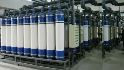
Ultrafiltration
Acts as a pre-treatment to remove suspended solids and protect downstream processes.
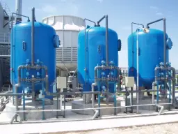
Media Filtration
Multimedia filters are essential water treatment solutions designed to remove suspended solids, turbidity, and particulate matter from water.
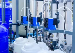
Chemical Dosing Systems
Introduces inhibitors and pH stabilizers to control microbial growing in water systems.
Advantages of Seawater Desalination
Seawater desalination offers numerous benefits, particularly for regions facing water scarcity or high demand. By transforming an abundant resource into usable freshwater, desalination provides solutions that address both immediate and long-term water challenges:
- Reliable Water Supply: Desalination systems ensure a consistent source of freshwater, independent of weather conditions or natural freshwater availability, making them invaluable for drought-prone areas.
- Scalability: From small coastal villages to large metropolitan cities, desalination plants can be designed to meet diverse water needs, ensuring flexibility and adaptability.
- Quality Assurance: Advanced desalination technologies produce water that meets or exceeds stringent potable water standards, supporting health and safety requirements.
- Drought Resilience: By reducing dependency on traditional water sources, desalination enhances resilience against prolonged droughts and water shortages.
- Economic Growth: Reliable access to water supports industrial and agricultural activities, driving economic development in regions where water scarcity might otherwise limit progress.
Technological Advancements in Seawater Desalination
Modern seawater desalination technologies are evolving rapidly, making the process more efficient, sustainable, and affordable. Key innovations include:
- Advanced Membranes: Cutting-edge membranes offer improved durability, enhanced salt rejection rates, and lower energy requirements, making desalination systems more efficient and cost-effective.
- Solar-Powered Desalination: Integrating renewable energy sources, such as solar power, reduces reliance on fossil fuels and minimizes the carbon footprint of desalination plants.
- Hybrid Systems: Combining reverse osmosis with thermal processes maximizes water recovery rates and reduces energy consumption, optimizing the overall performance of desalination plants.
- AI and IoT Integration: Real-time monitoring and predictive analytics allow operators to detect and resolve issues proactively, ensuring consistent system performance.
- Low-Pressure RO: Innovative low-pressure reverse osmosis systems achieve high recovery rates with significantly reduced energy consumption, lowering operational costs.
Challenges and Solutions in Seawater Desalination
Despite its benefits, seawater desalination faces challenges that require innovative solutions:
- High Energy Consumption: Energy recovery devices and the integration of renewable energy sources, such as wind or solar power, significantly reduce operational energy demands, making desalination more sustainable.
- Brine Disposal: Brine, a byproduct of desalination, can pose environmental risks if not managed properly. Advanced brine management systems, including zero-liquid discharge technologies, mitigate these impacts effectively.
- Scaling and Fouling: Pre-treatment technologies, such as ultrafiltration and antiscalant dosing, protect desalination systems from scaling and fouling, ensuring reliable operation and prolonging system lifespan.
FAQs about Seawater Desalination
- How efficient are modern desalination systems? Current technologies, especially reverse osmosis, achieve up to 50% water recovery rates with reduced energy consumption.
- Is desalinated water safe for drinking? Yes, desalinated water meets international drinking water standards when properly treated and monitored.
- What are the environmental concerns with desalination? Energy usage and brine disposal are key concerns, but modern advancements address these issues effectively.
- How long do desalination systems last? With proper maintenance, most systems have a lifespan of 20-30 years.
- Can desalination be combined with renewable energy? Yes, solar-powered and wind-assisted desalination systems are increasingly being deployed to enhance sustainability.
Seawater Desalination and Reverse Osmosis Systems
The reverse osmosis (RO) method based on membrane technologies is the most widely used method in desalination facilities. Reverse osmosis is based on the principle of removing dissolved salts and other impurities by passing water through a semi-permeable membrane under high pressure. This method has been found to be advantageous in terms of energy efficiency and scalability compared to alternatives such as thermal distillation and has become approximately 66% of the world's desalination capacity as of the 2010s. Modern seawater RO facilities can reduce energy consumption to levels such as ~3 kWh for a unit volume of water purification thanks to energy recovery units and advanced membranes. This report explains in detail the stages of reverse osmosis systems in seawater purification, the types of filters and membranes used, chemical processes and the parameters to be monitored in the process.
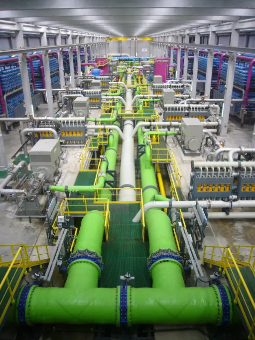
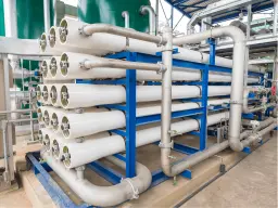
Figure 1: The reverse osmosis unit at the El Prat desalination plant near Barcelona, Spain. The large green pipes represent high-pressure feed lines, while the blue cylindrical bundles in the background represent spiral-wound reverse osmosis membranes. Plants of this scale can convert hundreds of thousands of cubic meters of saltwater into drinking water per day.
Stages of the Reverse Osmosis Process
Seawater treatment by reverse osmosis consists of several successive process steps, from the reception of raw water to the distribution of purified product water. The main stages of a typical seawater reverse osmosis plant and the functions of each are described below:
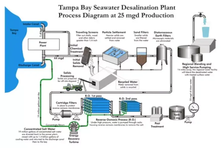
Figure 2: Flowchart of a typical seawater reverse osmosis plant (Tampa Bay, 25 mgd capacity). This diagram shows all steps from water intake and pretreatment to two-stage RO membrane processes and final posttreatment. After the seawater is removed from the plant by coarse screens and sedimentation, large and heavy solids are removed and then passed through sand and diatomaceous earth filters to remove fine particles. The water, which passes through cartridge filters, is then fed to the RO membrane by high-pressure pumps and is separated from its salts and converted into product; the concentrated salty stream is removed by the energy recovery turbine and the treated water is subjected to final balancing processes.
1. Water Intake and Initial Filtration
The seawater treatment process begins with the intake of raw water from the sea. In the intake of water from the open sea, large sediments and organisms such as leaves, algae, and wood fragments are usually captured using traveling screens or coarse sieves in the intake structure . For example, in the Tampa Bay facility, objects such as shells and branches larger than 1/4 inch (>6 mm) are eliminated at this stage. Following coarse filtration, biological growth can be controlled by applying a chemical pretreatment such as low dose chlorine in the water intake structure (to prevent algae and marine organisms). The water is then conveyed to the pretreatment units within the plant. The main purpose of the raw water intake stage is to provide a relatively stabilized water intake by removing large-grained contaminants in order to protect the subsequent sensitive equipment and membranes.
2. Pre-treatment (Coagulation, Sedimentation and Filtration)
Pretreatment is a critical step for the efficient and long-lasting operation of reverse osmosis membranes. Seawater contains many suspended solids, turbidity, organic matter and microorganisms. If these contaminants are fed directly to the membranes, they will accumulate on the membrane surface and cause clogging (colloidal fouling), biological growth (bio-fouling) and scaling problems. Therefore, the feed water must be cleaned as much as possible before entering the membranes. A reliable pretreatment technique is a prerequisite for the successful operation of the SWRO process and aims to minimize particle, organic and biological fouling on the membranes.
The first step in pretreatment is usually chemical coagulation and flocculation . By adding coagulants such as metal salts (e.g. iron(III) chloride or aluminum sulfate) and polymers to the water, fine suspended particles, plankton and organic matter in the water are coagulated. Microorganisms and colloids are bonded together to form flocs with these chemicals. Then, the water is slowly passed through a balancing/sedimentation tank to settle the formed flocs ; during this process, heavy particles settle to the bottom and are separated from the water. By adjusting the chemical conditions correctly (pH, coagulant dose, etc.), dissolved organic matter can also be partially adsorbed and attached to the flocs.
rapid sand filters or multi-media filter columns are used to remove smaller and lighter particles from the water . These filters contain media such as quartz sand, anthracite or garnet with special grain sizes. As the water is filtered from the top down through the filter bed, most of the remaining suspended solids are trapped between the grains. The turbidity of the water leaving a typical granular media filtration stage can be reduced to ~0.1 NTU. If the filtered water still contains very fine (submicron) colloids, some systems use additional auxiliary filters. For example, at the Tampa Bay facility, a diatomaceous earth filter is applied after the sand filter to retain micron-sized colloidal material. Diatomaceous earth (kieselguhr) filters can filter even very fine particles by passing the water through a porous soil material bed.
Finally, just before entering the RO membranes, the water is passed through cartridge filters . Cartridge filters are fine cylindrical filter elements with pore sizes typically 5 microns or smaller. They serve to protect the membranes by capturing the last remaining sediment particles that may have escaped from previous steps. In a sense, cartridge filters are placed as final safety filters and help to reduce the Silt Density Index (SDI) of the membrane inlet water below a certain level. Seawater RO systems are generally designed to have a feedwater SDI < 3; modern plants aim for SDI < 2. For example, an advanced pretreatment sequence (coagulation + dissolved air flotation + filtration) can reduce raw water turbidity from 5–20 NTU to <0.25 NTU and an SDI of ~1.5. The lower SDI allows the membranes to resist fouling for longer periods of time and to operate at their original design capacity.
Note: As an alternative to classic sand filter pretreatment, low-pressure membrane pretreatment applications have become widespread in many facilities in recent years . Microfiltration (MF) or ultrafiltration (UF) membranes can replace sand filters in difficult source waters such as seawater. This type of pretreatment reduces turbidity and SDI values in the water to much lower levels (SDI < 2 or even < 1) and provides almost completely clear water to the RO membranes. With UF/MF pretreatment, it is easier to operate the RO unit stably, especially in coastal waters with algae blooms or turbidity fluctuations. However, membrane pretreatment also has its own maintenance requirements, such as the need for chemical cleaning; the method to be selected depends on the raw water quality and operating conditions.
A well-designed and operated pretreatment prepares the RO feed to target values such as turbidity <0.5 NTU and SDI <3 . This minimizes the accumulation of fouling and biological film on membranes, reduces the frequency of chemical cleaning, and reduces overall operating costs.
3. High Pressure Pump and Energy Recovery
The clear and relatively low particle content seawater that has undergone pretreatment is now ready to be desalinated through the reverse osmosis membranes. However, in order to overcome the osmotic balance and force the water molecules through the membrane, high pressure is applied to the water. For this purpose, high pressure pumps come into play. A typical seawater RO system requires an operating pressure in the range of approximately 60–70 bar . Values such as 69–80 bar are given in the literature for conventional SWRO pumps. In practice, pressures between 55 bar and 80 bar are used, depending on the salinity of the feed water and the desired recovery rate. For example, for seawater with a salinity of 35,000 mg/L (3.5% salt), a pressure of ~65–70 bar may be sufficient to remove half of the water as fresh water (approximately 45–50% recovery). The pressure will increase if higher salinity or higher recovery is desired.
The water coming out of the high pressure pump is fed to the membrane modules placed in series inside the steel membrane housings (pressure vessels). While the feed water flows through the membrane elements from the point of entry to these vessels, some of the water is filtered through the membranes and passes to the collection pipe (permeate tube) inside due to the applied pressure. In this way, fresh water is obtained, while salts and other retentate remain on the inlet side of the membranes and condense during the flow. Each pressure vessel typically houses 5–8 spiral wound membrane elements ; the salt concentration increases as the water moves from the first element to the last element. For this reason, systems are usually designed in multiple stages : The concentrate (remaining salt water) in the first stage is used as the feed for the next stage, thus increasing water recovery.
The reverse osmosis process is an energy-intensive process. Most of the pressure given to the water remains on the concentrated flow, and if this energy is wasted, operating costs increase. To prevent this, energy recovery devices (ERD) are used in modern RO plants. The concentrated flow passes through these devices as it leaves the system with high pressure and transfers its energy to the newly arriving feed water. For example, ERDs (isobaric devices) of the pressure exchange chamber type or hydraulic turbines such as the Pelton turbine can recover ~90% of the concentrated flow pressure. In this way, the energy requirement of the high-pressure pump is significantly reduced. Today, thanks to high-quality ERD units, the energy consumption of seawater reverse osmosis has been reduced to approximately 3 kWh/m<sup>3</sup>, very close to the theoretical minimum . This progress is quite striking when you consider that RO plants 20-30 years ago consumed 5–8 kWh/m<sup>3</sup>. In short, high pressure pumps and energy recovery equipment work together to form the power source and efficiency enhancing core of the RO process .
4. Reverse Osmosis Membrane Stage
The heart of the reverse osmosis system is the membrane modules . Almost all of today’s seawater desalination plants use thin-film composite (TFC) polyimide/polyamide membranes . These membranes consist of an extremely thin (<0.5 µm) polyamide separator layer on a microporous support layer (usually polysulfone). The pore diameters of polyamide membranes are in the angstrom range (~0.0001 microns), allowing water molecules to pass through while impermeable to dissolved salt ions and larger contaminants. According to Tampa Bay plant data, the pore size of the RO membranes used is approximately 0.001 microns , or 100 thousandths of a human hair. In this way, ions such as sodium and chloride are retained at a rate of 99%+, while H<sub>2</sub>O molecules can pass through.
The membranes are typically packaged in a spiral-wound module configuration. In a spiral-wound RO element, flat leaf membranes and flow channel separator meshes are wrapped around a center collection tube. Each membrane leaf is glued on three sides, with the remaining edges connected to the center tube. As the feed water flows through the channels between the membrane leaves at high pressure, some of the water passes through the envelopes to reach the center (permeate tube); the remaining water flows to the element outlet as a more saline concentrate. The flow diagram in Figure 2 shows this process in two stages (RO 1st pass and 2nd pass). Although a single-pass system is generally sufficient for seawater treatment, in some cases two-pass RO can be applied to improve product water quality . The permeate water from the first-pass RO outlet is fed to a second RO set to further reduce its salt (e.g. to obtain very low conductivity water, <50 mg/L). In drinking water facilities like Tampa Bay, a single pass is typically sufficient to meet the required water standards (less than 500 mg/L TDS); however, in industrial ultrapure water applications, a double pass is common.
The salt retention rate of reverse osmosis membranes is usually above 99%. For example, a typical seawater membrane can obtain <0.5 g/L (500 mg/L) of product from a feed at 35 g/L salinity. The two main indicators of membrane performance are permeate flux (production rate) and salt rejection rate . These values vary depending on parameters such as pressure, temperature, and feed salinity. When high pressure is applied, the water flux through the membrane increases and the salinity of the permeate decreases (salt permeation decreases). As the temperature of the water increases, the flux increases because the viscosity decreases, but the tendency for salt ions to leak through the membrane also increases slightly. The detailed effects of these parameters will be discussed in the following sections.
Seawater RO membranes are sensitive to chlorine and oxidants due to their material . Since the polyamide layer can be quickly oxidized and damaged by free chlorine, disinfectants such as chlorine used in pretreatment are completely removed before entering the RO membranes. For this purpose , reducing chemicals such as sodium bisulfite (NaHSO<sub>3</sub>) are dosed into the feed water before the membrane to neutralize the residual chlorine. Alternatively, in some systems, disinfection with chloramine is performed instead of chlorination, which has less damage on polyamide; however, this is generally not desired and most SWRO systems manage biological control in the form of short-term chlorination + full dechlorination in pretreatment. Although cellulose acetate -based membranes were used as membrane materials in the past, they are not preferred today because they have lower salt rejection and flux values; in addition, cellulose membranes are difficult to operate since they require continuous chlorination. As a result, almost all membrane elements in modern RO plants are of the TFC polyamide type and their operation is carried out considering their sensitivity.
Regular monitoring and maintenance are also essential to obtain the desired efficiency from RO membranes. Over time, fouling may occur on the membrane surfaces: In cases where pretreatment is insufficient, colloidal siltstone, biofilm or inorganic sediments (e.g. scales such as CaCO<sub>3</sub>, CaSO<sub>4</sub>) cover the membranes, reducing the flux and impairing the effluent quality. In this case, RO units are periodically subjected to chemical cleaning (CIP: Cleaning in Place) . Special cleaning solutions containing acids, bases or disinfectants are circulated through the membrane modules to dissolve accumulated dirt. Although membrane manufacturers usually recommend CIP every 3–6 months , it is ideal to perform cleaning when fouling indicators exceed certain thresholds (these indicators are discussed in the parameters section in the next section). For example, some manufacturers recommend starting chemical cleaning when the permeate flow rate decreases by 10% or salt permeation increases by 5–10% . Regular CIP can restore membrane performance to a large extent, but in cases of severe fouling/scaling, membrane replacement may be necessary. Therefore, continuous monitoring of the operation and preventive cleanings are critical.
5. Post-Treatment (Product Water Stabilization and Disinfection)
The permeate (product water) from a reverse osmosis unit is essentially pure water that has been largely desalinated. Typical seawater permeate can be both corrosive and have a flat taste when used directly as drinking water because it contains very little total minerals . Therefore, RO effluent is usually subjected to a series of post-treatment processes to stabilize and bring it into compliance with the standards.
First of all, some gases that are not removed during RO (such as CO<sub>2</sub>) may remain in the product water and make the water acidic. The pH of the permeate water is typically slightly acidic at 5.5–6.5 (as the bicarbonates in the feed water are converted to CO<sub>2</sub> gas). This acidic water can dissolve metals in the transmission lines. Neutralization and mineral addition are used to prevent this and to provide mineral balance to the water. The most common method is to pass the water through a bed of limestone (calcite) . This bed, which contains calcium carbonate minerals, increases the pH of the water and adds ions such as Ca<sub>2+</sup> and HCO<sub>3</sub><sup>-</sup>, making the water more balanced and alkaline . Alternatively, hardness and alkalinity can be adjusted in a similar way by dosing with lime (Ca(OH)<sub>2</sub>) or soda ash (Na<sub>2</sub>CO<sub>3</sub>). The aim is to reach the recommended pH range of 7–8 and a certain level of hardness for drinking water.
In addition, product water is usually disinfected at the final point . Since the membranes retain bacteria and viruses to a large extent, the permeate is microbiologically quite clean; however, since there is a risk of re-contamination during transport and storage, low-dose chlorination with chlorine or chloramine is used to ensure biological safety of water in the distribution network. UV disinfection can also be used in some systems, but since it does not provide residual protection, it is generally preferred to pump some chlorine. It was stated that balancing chemicals are added to the product water after RO in the Tampa Bay facility and the resulting high-quality water is sent to the regional network facility and mixed with other treated waters. With the mixing and final adjustments, final water that complies with all parameters in the drinking water regulations is obtained.
Another aspect of post-treatment is wastewater (concentrate) disposal . In the RO process, a certain percentage of the feedwater is converted to fresh water (recovery rate is usually 35–50%), while the rest exits as a more saline concentrated stream. This saline concentrate is typically discharged back to the sea or the environment. However, since direct discharge can cause environmental problems, a dilution or controlled discharge method is usually used. For example, the concentrate discharged from the Tampa Bay plant is mixed with the cooling water of the neighboring thermal power plant and discharged to the sea, so that the salt concentration does not rise suddenly in the receiving environment. In many plants, the discharge is made through diffuser pipes on the seabed, and the concentrate is rapidly diluted over a large volume. The approximate salinity of the concentrate stream is about twice that of the seawater it is fed to (e.g. 35 g/L feed with 45% recovery → ~65 g/L concentrate). This stream usually exits with a slightly elevated temperature (the pumping process causes heating). For this reason, environmental impact assessments are made and the most appropriate discharge method is selected.
Finally, as part of post-treatment, the treated water is usually taken to the product water tank within the facility and pumped from there to the network. If the product water is to be mixed with water from different sources (blend), it is blended in the appropriate ratio. The final drinking water, which has undergone all balancing and disinfection processes, is now ready for distribution.
Parameters Measured and Controlled in the Process
In order to operate reverse osmosis systems efficiently and safely, certain critical operating parameters must be continuously monitored and controlled . These parameters are important both for monitoring system performance and for intervening early in potential problems. The main quantities measured in seawater RO processes and their interpretation are explained below:
- Pressures (Feed, Concentrate, Differential): The feed pressure at the outlet of the high-pressure pump is the force applied to the membranes and is typically in the tens of bars for SWRO. Some pressure drop occurs across each pressure vessel; the difference between the inlet and outlet is monitored as the differential pressure (ΔP) . Under normal conditions, a pressure drop of a few bars is seen across the first stage membranes of an RO system. If ΔP increases over time, it may indicate that the membranes or spacer networks are fouled and blocked. For example, a 15% increase in the first stage ΔP is usually considered a maintenance/cleaning alarm. Operators monitor the ΔP for each stage separately to see where the fouling begins. Abnormally high feed pressures are also an indication of membrane fouling or pump failure. The concentrate outlet pressure is monitored for energy recovery unit performance. In optimum operation, most of the concentrate pressure is transferred to the ERD and is not wasted.
Flow Rates and Recovery Rate: There are three basic flows in the system: Feed flow , permeate flow and concentrate flow . The relationship between these is expressed by the recovery rate :  Recovery(%)=Feed flowPermeate flow ×100. Recovery is generally selected in the range of 35–50% in seawater systems. High recovery means less wastewater, but it also leads to more concentration of salts during the feed and increases the risk of scaling. As recovery increases, the osmotic pressure effect on the membrane increases; after a certain point, net water flow may come to a standstill. Therefore, excessively high recovery is not targeted. In operation, the change in permeate flow compared to design values is a critical indicator. A decrease in permeate flow may indicate that the membranes are starting to foule or that pump performance is decreasing. Membrane manufacturers recommend cleaning when a 10% decrease in flow occurs compared to the initial value. Similarly, abnormally low permeate flow rates may indicate a problem with the feed pump or valves, so regular calibration and monitoring of all flow meters is essential.
- Salinity, Conductivity, and TDS: The salt concentration (TDS, in mg/L) or electrical conductivity (µS/cm) of the feed water and permeate product are measured continuously or periodically. Conductivity is an indirect indicator of the amount of dissolved ions in the water and is used to monitor reverse osmosis efficiency. The salt removal efficiency of membranes can be calculated with the formula:  Salt Removal(%)=(1−Feed TDSPermeate TDS)×100. A new and clean SWRO membrane usually provides 99% or more salt removal. For example, if 200 mg/L of permeate is taken from 35,000 mg/L of feed, this means 99.4% removal. If permeate conductivity starts to increase in the plant, the performance of the membranes may be decreasing. This may occur when some ions start to leak due to chlorine damage (active layer oxidation) or fouling in the membranes . In particular , a sudden and sharp increase in conductivity may indicate a ruptured membrane or a leaky O-ring, which may indicate that the raw water is mixed in – in such a case, the components in the relevant pressure vessel should be checked. A slow increase in conductivity over time generally indicates that the membrane surface is fouled and the effective pore area is reduced, which means that the salt retention rate is reduced. According to the manufacturer’s recommendations, a 5–10% increase in permeate conductivity (or salt permeation) indicates that it is time for cleaning. The salt permeability may also increase slightly with ageing of the membranes, but this is usually very slow; rapid changes indicate a problem. Consequently, both feed and product water conductivity should be monitored and recorded with online sensors.
- pH and Chemical Condition: The pH of the feed water and permeate is important for both chemical control of the process and for scalent formation. The pH of the feed water is usually slightly lowered depending on the anti-scalant dosage strategy (for example, the natural pH of seawater is 8.2, but to reduce the scaling tendency, it can be lowered to around pH 7 with mineral acid). Therefore, the pH of the water entering the pump is constantly measured and maintained within the desired range. An increase in pH can mean failure or chemical depletion of the metering pumps and increases the risk of calcium carbonate precipitation. Conversely, excessively low pH is undesirable as it can accelerate corrosion. The pH of the permeate water is also monitored; if too low, it may indicate insufficient neutralization in post-treatment. pH sensors also provide critical feedback in membrane cleaning processes (acid/base circulation during CIP).
- Silt Density Index (SDI) and Turbidity: The most important indicators of pretreatment quality are SDI and turbidity measurements. SDI is an index based on the clogging time of a specific filter paper and numerically expresses the colloidal fouling potential of water. Standards generally require SDI < 5 for RO feed; SDI < 3 is targeted for difficult applications such as seawater, and SDI < 2 indicates very good pretreatment. SDI tests are performed at certain intervals (e.g. daily) in the facility to verify the performance of the pretreatment. If the SDI value is unusually high, there is a problem in the filtration system (e.g. filter rupture, coagulant dosage error) and immediate intervention is required because high SDI can cause rapid clogging of membranes. Turbidity (NTU) is a parameter that can be monitored in real time; RO inlet turbidity is generally kept below 0.2–0.5 NTU. Online turbidity meters give an alarm when there is a sudden deterioration in water quality (e.g. plankton bloom or sludge migration). This way, operators can take precautions such as slowing down or stopping the system and backwashing the filters if turbidity increases. In short, SDI and NTU are health indicators of the pretreatment; staying low all the time guarantees long life for the membranes.
- Temperature: Water temperature is an important factor affecting membrane performance. Warmer water increases membrane permeability, thus increasing flux, but it can also increase salt migration to some extent. Conversely, when seawater temperature drops in cold winter months, permeate flow rate obtained at the same pressure decreases. Therefore, large facilities are designed taking into account seasonal water temperature changes; in order to compensate for the decreased flux in winter, it may be necessary to either increase the pressure slightly or to put additional membrane elements into operation. Temperature is generally not a controllable parameter (because seawater temperature is an environmental factor); however, it is important to measure it and normalize the performance data according to temperature. For example, membrane manufacturers give a performance guarantee for 25°C; we can understand the real membrane status by normalizing the efficiency obtained in 15°C water in the facility to 25°C. For this purpose, instantaneous temperature is recorded with digital temperature sensors in the system and other parameters are compared accordingly.
- Chlorine/ORP: If chlorine is added to control biological growth during the pretreatment phase, the chlorine must be completely neutralized before reaching the RO inlet. Therefore, it may be necessary to perform a chlorine measurement (or ORP: Oxidation reduction potential measurement) just before the membrane. The free chlorine level should be 0.0 mg/L. If even trace amounts of chlorine are detected in the measurements, this situation must be corrected immediately (increase the dosage of the reducing chemical or reduce chlorination); otherwise, irreversible damage to the membranes may occur. ORP sensors provide a rapid indication of the presence of chlorine residue by instantly monitoring the oxidation level of the water. This parameter is especially used to verify that the chlorine dosing/neutralization balance is working correctly.
many more data can be collected depending on the system design and operation (e.g. conductivities at each pressure vessel outlet, inlet/outlet pressure differences of each filter, UV transmittance if there is a UV disinfection system, etc.). However, values such as pressure, flow, conductivity, pH, SDI/turbidity are indicators that every RO operator closely follows. These data are usually continuously recorded with a SCADA system and trend analyses are performed. Monitoring performance trends allows for foreseeing when membranes will need cleaning or if there is a problem in the pretreatment. For example, if an operator only starts maintenance when a problem occurs in a system, it has been reported that non-return channels can be observed in membranes when cleaning is performed only when the ΔP increase reaches 40–50 psi (3–4 bar). Therefore, proactive monitoring and early action are key to the efficient operation of RO plants.
The following table provides summary values of some important parameters typically monitored in the seawater reverse osmosis process:
| Parameter | Description / Importance | Typical Values / Limits |
|---|---|---|
| Feed Pressure | Pressure provided by the high pressure pump at the RO inlet. | ~55–70 bar in sea water (design dependent). |
| Differential Pressure (ΔP) | Pressure drop across each stage increases with increasing fouling. | 1–2 bar in clean start; 15–20% increase maintenance signal:contentReference[oaicite:49]{index=49}. |
| Permeate Flow Rate | Produced fresh water flow; shows membrane flux performance. | According to the design; A 10% drop indicates membrane fouling:contentReference[oaicite:50]{index=50}. |
| Recovery Rate | What percentage of the feed water was permeated? | SWRO: 35–50% (higher values indicate a risk of fouling/scaling):contentReference[oaicite:51]{index=51}. |
| Permeate Conductivity | Amount of ions in the product water; an inverse indicator of salt retention efficiency. | <500 µS/cm (~<300 mg/L TDS for drinking water).< An increase in value indicates a decrease in membrane performance. |
| Salt Removal | Salt retention efficiency of membranes (%). | SWRO is generally between 99–99.7%. A 1% decrease means a noticeable performance loss. |
| Feed SDI | Feed water colloidal pollution index (fouling indicator). | Desired <3 (ideal <2). If it is high, pretreatment is insufficient:contentReference[oaicite:52]{index=52}. |
| Turbidity (NTU) | Feed water turbidity; indicator of suspended solids. | <0.5 NTU (<0.1 NTU with UF). Permeate: <0.1 NTU (usually close to zero). |
| pH (Feed/Permeate) | Acidity-alkaline; important for scaling and corrosion control. | Feed ~7–8 (controlled), Permeate ~5.5–6.5 (neutralized in post-treatment). |
| Cl2 (Free Chlorine) | Residual oxidant at membrane inlet; intolerant for polyamide. | 0 mg/L (none). Any detection requires immediate action:contentReference[oaicite:53]{index=53}. |
| Temperature | Water temperature affects flow and viscosity. | 25°C reference. A 5°C drop can reduce flux by ~15–20% (correction factors are used). |
The values above are generally considered typical ranges for seawater reverse osmosis systems. Each facility may have its own design parameters and goals; therefore, “normal” values may vary from project to project. The important thing is to determine the baseline values for your own system during operation and follow the trend accordingly . For example, the pressure, flux, and conductivity values recorded during the first operation with new clean membranes serve as a reference over time. When a certain deviation threshold is exceeded, operators receive an alarm and intervention plans are put into effect. With this approach, small problems are solved before they become big, membrane life is maximized, and product water quality is constantly kept safe.
Conclusion and Evaluation
Reverse osmosis technology in seawater desalination is an integrated process that extends from pretreatment to high-pressure membrane filtration and final water quality regulation . Each stage determines the overall efficiency of the system by preparing the appropriate conditions for the next. Rough filters and pretreatment condition the inlet water by protecting the membranes; spiral wound polyamide membranes separate the water from its salts under pressure; post-treatment balances the obtained pure water and prepares it for use. Monitoring critical parameters such as pressures, flow rates, conductivity, pH, SDI throughout this process is vital to maintain system performance.
Academic and industrial studies show that reliability of pretreatment and regular operational control are essential for a successful SWRO operation. As Valavala et al. stated, it is essential to use reliable pretreatment techniques (coagulation+filtration or UF/MF) in SWRO processes due to membrane fouling risks.
Again, with the use of energy recovery devices in modern facilities, energy costs have been significantly reduced and obtaining fresh water from seawater has become more sustainable. Reverse osmosis membrane technology has also developed over the years and has been improved to achieve high efficiency at low pressures. For example, thin film composite membranes provide drinking water for millions of people today with salt rejection exceeding 99% and high permeate fluxes. As a result, reverse osmosis systems in seawater treatment provide a reliable and continuous source of fresh water when designed and operated correctly. Mastering the details of each stage discussed in this report is critical for engineers and operators to ensure efficient operation of the system. With the right pretreatment, appropriate membrane selection, effective process control and regular maintenance, reverse osmosis plants can operate stably for years and successfully convert seawater into potable water. Thus, seawater can be considered an inexhaustible reservoir for populations living in regions or on islands where water resources are limited. The knowledge-intensive yet practical applicability of reverse osmosis makes it a strategic water supply technology for today and future generations.
Sources: Information and data were compiled from a variety of academic publications, technical reports, and industry guides. For example, Valavala et al. (2011) provided a comparison of RO pretreatment techniques, while Tampa Bay Water Authority reports provided a flowsheet and operating data for a real SWRO plant. Membrane performance parameters were compiled from technical sources such as Lenntech, while practical information on interpreting operating indicators was obtained from publications by industry experts such as Chemtreat. This holistic approach aims to provide a comprehensive overview of seawater reverse osmosis processes by combining both theoretical background and practical experience.