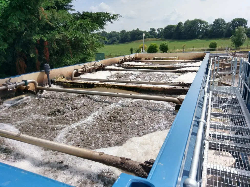
MBBR Wastewater Systems
MBBR (Moving Bed Biofilm Reactor) systems are an advanced wastewater treatment technology designed to efficiently handle municipal and industrial wastewater. Utilizing a unique moving bed biofilm process, these systems provide high performance in removing organic matter, nitrogen, and phosphorous. Their compact design and low operational costs make them ideal for upgrading existing wastewater treatment plants or implementing new solutions in limited spaces. MBBR systems are known for their durability, flexibility, and ability to operate under varying load conditions.
This technology is particularly effective in industries with high organic loads such as food and beverage, textile, and pharmaceuticals. With minimal maintenance and energy requirements, MBBR systems offer a sustainable and cost-effective solution for meeting stringent environmental regulations. Search terms like "efficient wastewater treatment," "industrial water treatment solutions," and "biofilm reactor advantages" are often associated with MBBR systems, making them a leading choice for modern wastewater management.
MBBR Product Series
Check our product groups designed for your needs
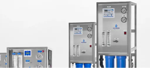
Small-Scale Systems
Compact and efficient MBBR systems designed for residential areas and small-scale commercial use. Ideal for limited spaces and moderate wastewater loads.
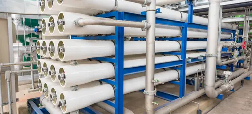
Industrial MBBR Systems
igh-capacity MBBR solutions engineered to handle industrial wastewater with heavy organic loads. Perfect for industries like food processing, pharmaceuticals, and textiles.
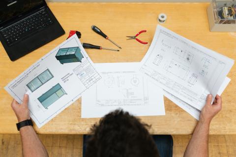
Custom-Designed MBBR Systems
Tailored MBBR systems created to meet unique operational needs or regulatory requirements, ensuring the best performance for specific applications.

Small-Scale MBBR Systems

Phosphorus Removal Systems
Phosphorus is a major contributor to eutrophication in water bodies, leading to harmful algal blooms. MBBR systems effectively remove phosphorus using biological and chemical processes, ensuring compliance with stringent environmental regulations.
Groundwater Treatment Systems
Contaminated groundwater often contains organic pollutants and nitrogen compounds. MBBR systems provide a compact and efficient solution for treating groundwater, delivering high-quality water suitable for reuse or safe discharge.
MBBR Systems for Industrial Usage
BOD/COD Removal Systems
MBBR systems are highly effective in reducing Biochemical Oxygen Demand (BOD) and Chemical Oxygen Demand (COD), breaking down organic matter in wastewater. These systems ensure the treated water meets environmental discharge standards.
Nitrification and Denitrification
For nitrogen removal, MBBR systems enable efficient nitrification (conversion of ammonia to nitrate) and denitrification (conversion of nitrate to nitrogen gas). This dual process minimizes nitrogen pollution in sensitive ecosystems.
Oil and Grease Removal
Industries such as food processing and oil production generate wastewater with high oil and grease content. MBBR systems efficiently remove these contaminants, protecting downstream processes and ensuring environmental compliance.
Custom-Design Systems For Your Needs
Discover tailored custom system solutions designed to meet your specific requirements. Enhance water quality and system performance with our customizable options today!

Phone
Address
Akçaburgaz, 3026. Sk No:28, 34522 Esenyurt/İstanbul TURKEY
MBBR Process Overview
MBBR (Moving Bed Biofilm Reactor) is an innovative biological process used in wastewater treatment. In this system, plastic carriers with high surface area circulate freely in the reactor and microorganisms grow in the biofilm layer formed on them. These microorganisms purify the water by breaking down organic substances, nitrogenous compounds and other pollutants in the wastewater. MBBR technology combines the advantages of classical activated sludge systems and fixed biofilm (e.g. trickling filter) systems. It has become popular in both industrial and domestic wastewater treatment with its advantages of high treatment efficiency, compact design (smaller tank volumes) and easy operation . Below, all stages of the MBBR treatment process are explained in detail, together with the parameters to be monitored at each stage, their interpretation and the equipment used. In addition, the application areas of MBBR, typical pollutants that can be treated, discharge standards in Turkey and the EU, design criteria, design/operation tips and points to be considered are also discussed in detail.
Stages of MBBR Treatment Process and Parameters to be Monitored
An MBBR integrated wastewater treatment plant usually consists of pretreatment, primary treatment, biological treatment (MBBR reactors), secondary treatment (sedimentation) and if necessary advanced treatment & disinfection stages. At each stage, certain parameters are measured and interpreted to ensure the efficient operation of the process. Also, different equipment is used at each stage. Below is stage-by-stage information:
Preliminary Treatment
Pretreatment is the first step in removing large solids from the wastewater, such as sedimentable sand and oil. This step protects subsequent biological processes from sudden loads and physical damage.
Parameters to be Measured
Flow Rate: Input wastewater flow rate should be measured continuously. High flow rates can lead to flood risk and equipment overload, so they are monitored with a flow meter. Flow data is interpreted to take precautions or determine the balancing volume in case the design capacity is exceeded.
pH: The pH value of the influent wastewater is controlled. Especially in industrial wastewater, excessively acidic or basic pH can damage biological processes. The pH value should generally be kept between 6 and 9; if it is outside this range, measures such as neutralization are required.
Temperature: The wastewater temperature is measured. High temperatures (e.g. >40°C) can negatively affect microorganisms, while low temperatures slow down biochemical reaction rates. The measured temperature is interpreted to predict the performance of microorganisms operating in the biological stage.
Solid Waste Load: The amount of coarse waste retained in the screens and the amount of sand accumulated in the grit trap are monitored (daily volume or mass of removed waste). These parameters indicate the efficiency of the pretreatment. For example, if a large amount of solid waste is retained, it is interpreted that the pollutant load in the wastewater is high and disposal plans are arranged accordingly.
Main Equipment Used
Screens: Coarse and fine screens retain large solids (cloth, plastic, PET bottles, etc.) in wastewater. Mechanically cleaned screens are generally used. After the coarse screen, there is a fine screen with narrower gaps.
Grit Trap: It is the unit that separates inorganic particles such as sand and gravel in wastewater by settling them. It can be of air or non-ventilated (horizontal flow) type. The material accumulated in the grit trap is periodically cleaned.
Oil Separator: It is used to separate oil and grease found especially in industrial and kitchen wastewater by floating. The oil layer that rises to the surface is removed with scrapers.
Equalization Tank: There is usually a balancing tank after pretreatment to reduce fluctuations in flow rate and pollution concentrations. This tank ensures that the wastewater is homogenized and delivered to the biological unit with a constant flow by the pump. By using mixers in the balancing tank, solids are prevented from settling and the wastewater quality is balanced over time.
Pump Station: Pumps are used to send the wastewater from the pretreatment to the biological reactor(s) at the desired flow rate and pressure. Flow meters are usually located in pump stations or at the balance tank outlet.
Primary Settling
Primary treatment is the stage where suspended solids and some organic pollutants are removed by gravity sedimentation. In the MBBR process, primary sedimentation can be used depending on the flow rate and pollution load; its purpose is to reduce the load coming to the biological reactor.
Parameters to be Measured and Interpretation
Total Suspended Solids (TSM) Input/Output: The TSM concentration (mg/L) of the wastewater at the input and output of the primary sedimentation tank is measured. The input-output difference indicates how much suspended solids the primary treatment retains. For example, if the input TSM is 300 mg/L and the output TSM is 150 mg/L, it means that 50% suspended solids removal is taking place. High TSM removal means lower load in the next biological stage.
Chemical Oxygen Demand (COD) Input/Output: Except for some dissolved organics, some of the suspended organics can be removed by primary sedimentation. By measuring the inlet and outlet COD values, it is understood how much the primary treatment reduces the organic load. Typically, primary sedimentation can remove 20-30% of COD and 25-35% of BOD. If the primary treatment efficiency is low, it can be interpreted that the particulate organics in the wastewater are fine or that the retention time in the tank is insufficient.
Settled Sludge Volume and Properties: The volume and properties (density, water content) of the sludge accumulated at the bottom of the primary settling tank are monitored. An increase in sludge volume may indicate that the inlet load is high. The sludge age of the accumulated sludge is not important here (it is raw primary sludge), but tank efficiency decreases if excessive accumulation occurs. The sludge height/volume measured at regular intervals is used to determine pumping frequency.
Main Equipment Used
Primary Sedimentation Tank: It is usually a round (center-fed) or rectangular sedimentation basin. While the wastewater slowly moves through this tank for a certain Hydraulic Retention Time (HRT) (usually 1-2 hours), the solids settle to the bottom. There are slow-moving collector bridges on the surface of the tank; scrapers push the sludge at the bottom towards the center or a funnel and send it to the sludge removal line. Oil and foam on the surface are collected and removed by surface scrapers.
Mud Pump and Mud Pits: Raw primary sludge collected at the bottom of the primary tank is sent to the sludge processing unit (e.g. sludge thickener) by pump. Pump control is made to be activated when the desired maximum sludge accumulation in the tank is reached.
Measuring Equipment: Sample points for measuring TSS are usually located at the tank outlet. Online sensors (e.g. turbidity sensors) can also be used. Flow meters can also be located at the tank inlet or outlet.
Biological Treatment – MBBR Reactors
This stage is the heart of the MBBR process. Thanks to the biofilm that develops in the carrier media, oxidation of organic matter and removal of nutrients (nitrogen, phosphorus) occur in these reactors. Biological treatment is usually designed as a multi-stage reactor: For example, aerobic MBBR focused on carbon removal (BOD/COD removal) in the first stage, aerobic MBBR focused on nitrification in the second stage; or if total nitrogen removal is desired, anoxic MBBR + aerobic MBBR can be arranged in a sequential manner. Each reactor contains a certain percentage (% fullness) of plastic biofilm carriers.
Parameters to be Measured and Interpretation
Dissolved Oxygen (DO) Level: In aerobic MBBR reactors, DO is a continuously monitored parameter. Typically, dissolved oxygen is provided at a level of ~2 mg/L. A DO value below 1 mg/L indicates that there is insufficient oxygen and that organic matter degradation and nitrification will slow down. Excessively high DO (>4 mg/L) indicates energy waste. Operators adjust the blower capacity according to the value received from the DO sensors; thus, both efficient treatment and energy optimization are achieved. DO is particularly critical for nitrification (oxidation of ammonium to nitrite/nitrate) and should not fall below at least ~1.5–2 mg/L.
pH and Alkalinity: In biological reactors, pH is maintained between 6.5–8.5. Biochemical reactions (especially nitrification) consume alkalinity and can lower pH. pH is measured continuously; if pH drops to < 6.5, the nitrification rate drops significantly and, if necessary, alkaline chemical dosage (e.g. sodium bicarbonate or lime) is used. High pH (>9) can also harm microorganisms. Alkalinity monitoring is important for interpreting nitrification capacity – for example, the removal of 1 mg NH4-N by nitrification consumes ~7 mg/L CaCO₃ alkalinity, so external addition is required if influent alkalinity falls below a certain value.
Chemical Oxygen Demand (COD) and Biochemical Oxygen Demand (BOD5): COD/BOD values of the inlet and outlet water of the MBBR reactor are measured at certain intervals (daily composite samples). The inlet-outlet difference shows the organic matter removal performance of the biological treatment. For example, if COD is 500 mg/L at the MBBR inlet and 100 mg/L at the outlet, it is understood that 80% removal is achieved. If a lower than expected removal is observed (parameters are high), this may be due to insufficient carrier occupancy, low temperature, toxic inlet or insufficient oxygen - interpretation is made according to these results.
Ammonium Nitrogen (NH4-N) and Nitrate (NO3-N): Especially in systems targeting nitrification/denitrification, nitrogen compounds are regularly monitored. Ammonium (NH4⁺) concentration is measured at the aerobic MBBR outlet; high ammonium values (above expectations) indicate insufficient nitrification. The interpretation of this is that either sludge age (biofilm age) is insufficient, DO insufficient, or factors such as temperature/pH may be the cause. Nitrate (NO3⁻) is measured after denitrification if there is an anoxic denitrification stage; high nitrate indicates insufficient denitrification. If there is an anoxic reactor, Oxidation-Reduction Potential (ORP) measurement can also be made – a decrease in ORP to around ~-100 mV indicates that anoxic conditions are provided and that there is a suitable environment for denitrification.
Total Nitrogen (TN) and Total Kjeldahl Nitrogen (TKN): Total nitrogen analyses (TKN + NO2+NO3) are performed periodically to monitor the effluent quality. The TN value is to check the compliance of the treatment with environmental legislation (especially within the scope of the receiving environment discharge limits). High TN indicates either a lack of nitrification or denitrification and the process is reviewed.
Phosphorus (P) Compounds: Since MBBR systems alone do not remove much phosphorus, inlet/outlet orthophosphate or total phosphorus measurement is monitored if chemical phosphorus removal is integrated. High phosphorus values indicate the need for increased chemical dosage or additional treatment if necessary. (Note: Biological phosphorus removal is limited to MBBR, chemical precipitation is usually integrated.)
Continuous Observation and Other Parameters: Temperature in the biological reactor is also monitored (it may decrease in winter, especially in open pools). When the temperature decreases, it is observed and interpreted that the biological reaction rates decrease (e.g. nitrification rate slows down at <15°C). Odor and visual observation are also important: Operational observations such as surface condition of the carriers (biofilm color should be brown/beige; black color may indicate anaerobicization), foaming status (excessive foam may indicate excessive biological activity or surfactant presence) are also part of the parameter monitoring. If necessary, microscopic analyses can be performed to understand the microorganism composition on the biofilm (especially the presence of nitrifying bacteria, filamentous organisms, etc. can be examined).
Main Equipment Used
MBBR Reactor Tank: They are usually rectangular or cylindrical tanks made of concrete or steel. Each reactor is designed to hold water for the specified Hydraulic Retention Time (HRT) (e.g. ~4-6 hours for organic removal, additional 4-6 hours for nitrification, total HRT). Biofilm carrier media are located in the reactor. Carriers are typically cylindrical or specially shaped particles made of polyethylene-like material, ~1-3 cm in diameter. Since the density of the media is close to water (~0.95-0.98 g/cm³), they remain suspended in the water stream. The volumetric fill ratio of carriers in the reactor is usually in the range of 40-60% (~50% is a frequently used value in design). This means, for example, that a 100 m³ reactor will have a volume of ~50 m³ of carriers. Higher fills (above 70%) are not recommended because the mobility of the media and oxygen transfer may be restricted.
Ventilation System: Aerobic MBBR tanks have fine/coarse bubble diffusers at the bottom and blowers that press air into them. Diffusers perform two functions by continuously supplying air to the environment: (1) Providing oxygen (2) Ensuring homogeneous distribution of media through mixing. Diffusers are placed at equal intervals on the bottom so that there is no dead space throughout the tank. Blower capacity can be modulated according to the DO set value with automation. Anoxic tanks do not have blowers; instead, mechanical mixers are used to mix the water (to keep the carriers suspended).
Media Retaining Screens: At the outlet of each reactor tank, there are stainless steel strainers/sieves that prevent carrier particles from escaping while the water is being carried to the next section. These screens can be in the form of closely spaced (e.g. 3-5 mm) wedge wire screens or perforated sheets and are typically mounted at the reactor outlet in a vertical cylinder or flat plate form. Carrier media cannot pass through these screens and remain in the reactor, while the treated water flows freely through the screens. The screens may have a backwash system or brush cleaning at certain intervals to prevent media clogging.
Internal Recirculation Pump: If total nitrogen removal is targeted (nitrification + denitrification), an internal recirculation pump is used that returns the nitrate at the outlet of the aerobic (nitrification) reactor back to the anoxic reactor. For example, a flow rate of 200-400% of the nitrification tank effluent can be returned to the anoxic reactor. This pump carries nitrate-rich water to the anoxic section via a pipeline, where heterotrophic bacteria can use the organic matter to denitrify the nitrate. The performance of this equipment is critical for the desired total nitrogen removal; the relationship between the set recirculation rate and the outlet nitrate concentration is monitored.
Sensors and Measurement Devices: Online sensors are widely used in MBBR reactors. Equipment such as DO probe, pH probe, temperature sensor, ORP probe (in anoxic tanks) provide continuous data. The data of these sensors is transferred to the PLC/SCADA system, allowing the operator to monitor in real time. There are also taps/ports for taking samples when necessary (such as COD, NH4, NO3 measurements for laboratory analysis).
Secondary Clarification – Sedimentation
The water leaving the MBBR reactors contains biofilm particles and remaining suspended solids that are separated as a result of biological treatment. Secondary sedimentation is the process of clarifying the treated water by separating these solids from the water. There is no intensive sludge recycle cycle in the MBBR system as in the activated sludge process; however, microorganisms and fine suspended matter that have broken away from the biofilm must be sedimented and removed. Thanks to this stage, the outlet water has a low TSS that will meet discharge standards.
Parameters to be Measured and Interpretation
Suspended Solids (SS) and Turbidity: SS concentration in the secondary sedimentation tank outlet water is a critical performance indicator. Generally, <30 mg/L SS is targeted (for compliance with standards). Online turbidity meters can also provide continuous monitoring. If the outlet SS values increase (e.g. 50+ mg/L), this indicates that the sedimentation efficiency has decreased. As an interpretation, it can be understood that the load in the sedimentation tank is high, the hydraulic retention time is insufficient or there is a possible sludge leakage problem. If necessary, intervention is made by reducing the surface load in the sedimentation tank (reducing the flow rate) or by adding chemicals and improving floc formation.
Settling Solids and Sludge Volume Index (SVI): To assess the quality of secondary sludge, sludge volume index (SVI) can be measured in the laboratory at certain periods. This indicates the settling characteristics of the separated biofilm particles. SVI is typically lower in MBBR systems than in activated sludge systems because the flocs can be heavier and more compact. A high SVI (e.g. >150 mL/g) indicates poor settling and turbidity/residual sludge may remain on the water surface.
Surface Foam and Solid Accumulation: Observe whether there is accumulation (floating sludge layer) on the sedimentation basin surface. If present, this is typically associated with sludge aging or denitrification gas rising to the surface. In this case, surface skimmers should be in operation and the sludge holding time should be shortened if necessary.
Main Equipment Used
Secondary Settling Tank: Generally, circular shaped, large diameter settling tanks fed from the center are used. MBBR effluent is fed to the tank through a central distributor structure, solids settle to the bottom as the water flows slowly upwards and radially, and the treated water overflows from the upper perimeter weirs. The surface of the secondary tank has a slowly rotating bridge and scraper paddles; these sweep the bottom sludge towards the center and collect the floating sludge on the surface in a hopper. The sludge that settles to the bottom is essentially the residual biomass that has broken off from the biofilm and is withdrawn from the system as waste sludge. (Since there is no continuous return cycle in MBBR as in activated sludge, this sludge is typically directly discarded or minimally recycled.)
Lamella Separators (Optional): In order to save space, compact lamella sedimentation units can be used instead of the classical large sedimentation basin in some MBBR systems. In these equipment, the sedimentation surface is increased and more effective sedimentation is achieved in the same volume thanks to the inclined plate or tubular placements. The function is the same in terms of parameter monitoring (SKM removal).
DAF (Dissolved Air Flotation) (Optional): Especially in industrial applications, after biological treatment, very fine and light particles can be separated by floating them with air bubbles using the DAF unit. DAF can be used as an alternative or additional to secondary sedimentation. It includes a compressed air dosing system and scrapers as equipment. AKM measurements are also made at the DAF outlet and typically very low (<10 mg/L) solids can be achieved.
Sludge Pump: The sludge collected at the bottom of the secondary sedimentation tank is periodically withdrawn by a pump. This pump is usually activated at fixed time intervals and sends the accumulated excess biomass to the sludge processing units. In the MBBR system, this sludge is considered as “waste biofilm sludge”. A return pump (RAS) does not operate continuously as in the activated sludge system because most of the biomass remains on the carrier surfaces.
Measurement and Control Tools: There may be an AKM sensor or turbidity (NTU) sensor at the sedimentation tank outlet. In addition, the flow rate of the outlet water and, if necessary, the transmission rate to the chlorination/UV system are measured here. Operators perform periodic checks to monitor the status of the sludge on the surface; in some systems, remote observation can be made with surface camera systems.
Advanced Treatment and Disinfection (Tertiary Treatment & Disinfection)
The water obtained after MBBR + secondary sedimentation generally meets the regulatory standards for discharge to the receiving environment. However, in some cases, further treatment may be required: For example, filtration if very low suspended solids are desired, chemical treatment for phosphorus removal, pathogen removal by ** disinfection ** or special pollutant removal by advanced oxidation. This stage polishes the effluent quality and prepares the water for purposes such as reuse (irrigation, industrial water).
Parameters to be Measured and Interpretation
Turbidity and TUS (Post Filtration): If a sand filter, disk filter, etc. is used, the turbidity (NTU) of the filtration outlet water is measured. Typically, a very low turbidity of ≤5 NTU is targeted. This value is also critical for disinfection effectiveness (low turbidity increases the access of UV rays or chlorine to microorganisms). If high turbidity is observed, it is interpreted that there may be a blockage in the filter or a media problem and the backwash frequency is adjusted.
Phosphorus (P) Concentration: If chemical phosphorus removal has been performed (for example, a coagulant chemical was added near the outlet and a precipitation/filtration was performed), total phosphorus is analyzed in the treated water. Generally, 1-2 mg/L below is targeted according to the receiving environment standards. Chemical dosage (such as FeCl₃, Al₂(SO₄)₃) is optimized according to the measured value. If high phosphorus remains, it is concluded that the chemical dosage should be increased or a longer reaction time is required.
Microbiological Parameters: If disinfection is to be applied, coliform bacteria, E. coli or fecal coliform counts are tested periodically before and after. These parameters are critical for disinfection performance, especially if the treated water is to be reused or discharged into swimming water. For example, if total coliform <1000/100 mL is desired after chlorine disinfection, it is verified with measurements. If bacteria are detected above the limits, inadequate dosage or contact time problems are interpreted.
Chlorine Residual (If Available): If disinfection is performed with chlorine, free residual chlorine is measured in the outlet water. Dosing is generally done so that there is a free chlorine residual of ≥0.5 mg/L at the end of the contact time in the water. If the measured residual chlorine value is below this, the dosage is increased; if it is too high, chlorine removal (neutralization with sodium bisulphite) may be required before discharge.
UV Transmittance (If Applicable): In UV disinfection systems, the UV transmittance of water (% transmittance at 254 nm wavelength) is monitored. High UVT (>60-70%) is suitable for disinfection; if UVT is low (colored or organic matter-laden water), the dosage of the UV device may not be sufficient, in which case it is commented that pre-treatment/filtration should be reviewed.
Main Equipment Used
Filtration Units: Sand filters (pressure or gravity rapid sand filters), microfiber disc filters or cartridge filters are used to further clarify the water after MBBR + sedimentation. These equipments have periodic backwash systems. There is usually a filter feed pump before the filter and pressure indicators on the front (increase in pressure difference indicates filter clogging, automatic backwash is triggered at a certain difference).
Activated Carbon Filters (Optional): Granular activated carbon (GAC) filters are used in some systems to remove dissolved organics (color, odor, micropollutants). In this case, cylindrical columns are used as equipment and periodic carbon renewal is required. UV254 absorbance or specific chemicals can be monitored as parameters.
Disinfection Systems: Two common disinfection equipment are the chlorine dosing system and the UV disinfection unit. In the chlorine system, liquid sodium hypochlorite (NaOCl) or gaseous chlorine is dosed into the water; it includes a dosing pump and mixing equipment. In the UV system, there is a reactor tank/channel containing UV lamps; the water is exposed to UV rays as it flows through. Both systems serve to destroy the microbial load in the effluent. If chlorine neutralization is required, there may also be sodium metabisulfite dosing equipment. The UV unit has UV lamp sensors and alarm systems (it will alarm if the UV dose drops).
Advanced Oxidation (Optional): For very difficult to decompose pollutants (such as drug residues), advanced oxidation equipment such as ozonation, hydrogen peroxide + UV can be found. In these systems, equipment such as ozone generator, ozone contact tank, peroxide dosing pump, etc. are installed. These are for very special cases and parameter monitoring is done with O₃ dosage, redox value or target chemical substance analyses.
Sensors and Controls: There are instrumentation such as flow meters, pressure sensors, chlorine analyzers, UV sensors around the filtration and disinfection units. The automation of advanced treatment units takes actions such as starting backwash and increasing dosage according to these sensor data. For example, if the water quality changes in the UV system (such as increased turbidity), there may be an alarm or lamp power modulation according to the sensor data.
Sludge Treatment
As in every biological treatment plant, the sludge removed from the treatment stages in the MBBR process must be properly processed and disposed of. Screen waste and sand from the pretreatment are collected separately. Primary sludge is obtained from the primary treatment, and biological residual sludge is obtained from the secondary treatment. These are generally subjected to sludge thickening, stabilization and dewatering steps.
Parameters to be Measured and Interpretation
Sludge Solids Content (%): The solids content is measured at the feed and outlet of the thickener or dewatering equipment. For example, if the dry matter content of the dewatered sludge at the belt press outlet is 20%, this is a good performance. A low value indicates that the polymer dosage or press settings should be reviewed.
Sludge Volume: The daily sludge volume produced is recorded. If much more sludge is produced than expected, an abnormal situation in the wastewater character (very high-loaded wastewater) or excessive use of chemical doses may be considered. An extremely low sludge volume may indicate that the sludge is not collected sufficiently or is leaking from the system.
Stabilization Indicators: If an anaerobic digester or an aerobic sludge digestion reactor is used, parameters such as temperature, pH, volatile acid/alkalinity ratio (for anaerobic) are monitored. These indicate whether the sludge has become stable. For example, methane production is measured in anaerobic digestion; low methane production is interpreted as a digestion problem.
Decomposition Rate: The percentage of organic matter decomposition as a result of sludge stabilization can be calculated (organic matter in the incoming raw sludge – outgoing stable sludge / incoming * 100). This is used for performance monitoring.
Main Equipment Used
Thickener: Gravity or mechanical thickeners are used to reduce the water content of the sludge. Some of the water is removed by keeping the sludge in the gravity thickening tank; in mechanical (e.g. drum or belt thickener) systems, the separation of water is accelerated by polymer dosage.
Sludge Stabilization Reactors: In facilities where a high amount of biological sludge is produced, anaerobic digesters (which also produce biogas if available) or aerobic sludge digestion tanks are used for sludge stabilization. These reactors contain equipment such as mixers and heaters (kept at ~35°C mesophilic temperature for anaerobic).
Dewatering Units: In the final step, the stabilized (or not, in small facilities directly) sludge is solidified with dewatering presses. These are usually belt press, sludge centrifuge or filter press type equipment. With the addition of polymer chemicals, sludge flocs are enlarged and most of the water is separated with mechanical compression/centrifugal force. The resulting cake becomes solid enough (~15-25% dry matter) to be sent to the disposal area by sludge trucks. These equipments include subcomponents such as dosing pumps, pressure gauges and motor drives.
Disposal/Evaluation Equipment: The final product sludge is taken to sludge storage silos or containers. There are options such as composting, intermediate storage, burning in cement kilns or sending to a regular landfill as a disposal method. These stages may also be outside the boundaries of the facility, but in the integrated approach, they are all designed as a whole.
Application Areas and Industries of MBBR Technology
MBBR systems are applied in a wide range of applications, from domestic wastewater treatment to various industrial wastewater treatment. The flexible structure of this technology enables effective treatment of wastewater with high organic load and improvements to existing facilities. The main sectors where MBBR is used and the typical wastewater characteristics in each are summarized below:
Municipal (Domestic) Wastewater Treatment: MBBR is used in city and town wastewater treatment plants, especially in cases where space is limited or where it is necessary to improve the existing activated sludge plant. Domestic wastewater typically has a moderate organic load (BOD5 ~200-300 mg/L, COD ~400-600 mg/L, TSS ~200-300 mg/L). It also contains nitrogen (TKN ~20-60 mg/L) and phosphorus (~5-15 mg/L). MBBR can be designed to reduce these values to discharge standards. For example, a municipal MBBR system can reach BOD5 < 20 mg/L, NH4-N < 5-10 mg/L at the outlet. The compactness and ease of operation of MBBR are important advantages in domestic applications; it is widely preferred in small and medium-sized municipal facilities.
Food and Beverage Industry: The food industry (e.g. dairy, slaughterhouse and meat processing, breweries, confectionery/canning plants) produces wastewaters containing very high organic pollutants. These wastewaters often have high BOD/COD concentrations. For example, a dairy plant may have COD levels of 2,000-5,000 mg/L and BOD5 levels of 1,000-3,000 mg/L; slaughterhouse wastewaters often have BOD5 levels of 1,500-4,000 mg/L and also contain high nitrogen (total N can reach several hundred mg/L) from oil and grease and blood protein. MBBR has the advantage of being able to withstand high loadings and tolerate shock organic loads in such wastewaters. In typical food industry wastewater, MBBR can remove >90% of organics while also reducing nitrogen by nitrification. In addition, MBBR is used together with pre-oil retention in wastewater with high oil-grease content to minimize clogging and excessive biofilm accumulation problems. The widespread use of MBBR in the food industry is also due to its ability to tolerate seasonal load changes (e.g. during campaign periods).
Beverage and Fermentation Facilities: (Brewery factories, fruit juice facilities, wine production, etc.) In this sub-sector, wastewater generally contains high easily degradable BOD (e.g. in breweries, BOD5 is at levels of 1,000-2,000 mg/L, nitrogen and phosphorus are relatively low). MBBR can operate with high volumetric loadings (high OLR) in such wastewater and reduce BOD in a short time. For example, 95% BOD removal can be achieved in brewery wastewater with a single-stage MBBR. Since fermentation-related wastewater can be at a warm temperature (30-35°C), the temperature tolerance of MBBR is sufficient for this sector.
Textile Industry (Wastewater Containing Dye and Chemicals): Wastewater from textile dyeing, finishing and washing processes has high COD values (500-1500 mg/L or higher), but the BOD/COD ratio is generally low (i.e. the biodegradability rate can be around 40-60%). In addition, these wastewaters contain color, dye chemicals (azo dyes, reactive dyes), auxiliary chemicals (surfactants, salts). MBBR is used to reduce biodegradable COD in textile wastewater. A typical textile MBBR unit removes 70-80% of the COD, while additional chemical treatment may be required for the remaining color and refractory materials. Although nitrogen is generally low in textile wastewater (there may be nitrogen contribution from dye chemicals), the main role of MBBR is to reduce color and organic matter. In textile plants, MBBR is usually integrated with processes such as chemical treatment (coagulation) and/or ozonation. Its advantage is that microorganisms can easily adapt to shock dye loads thanks to the stable biofilm, even in wastewater with high toxicity potential.
Paper and Cellulose Industry: Wastewater from paper mills and cellulose plants is characterized by very high COD content (COD can be 5,000-10,000+ mg/L due to lignin derivatives, especially in cellulose production) and high suspended solids (fiber particles). The BOD/COD ratio in these wastewaters is low (i.e. the fraction that is difficult to decompose biologically is high). MBBR is generally used in the paper industry as a pretreatment (roughing filter) of high-volume wastewater or for capacity increase integrated with activated sludge (IFAS). For example, in a paper mill, an MBBR first stage can remove 50-70% of the COD and then perform supplementary treatment with an activated sludge process at the next stage. Typical parameters: Since the AKM is very high (1,000+ mg/L), prescreening/sedimentation is performed; MBBR is advantageous in this respect as it is resistant to clogging. Since water recovery can also be important in paper mills, MBBR+MBR (membrane bioreactor) hybrid systems are also used – MBBR reduces the organic load, and full filtration is provided by the membrane.
Petrochemical and Refinery: In oil refineries, petrochemical plants and chemical industry, wastewater contains a wide range of organic pollutants (benzene, phenol, toluene derivatives, VOCs) and oily compounds. COD can be high in such wastewater (1000-3000 mg/L), but there are also components that are difficult to biodegrade or may be toxic. MBBR promotes the biological transformation of difficult to decompose substances by providing a balanced biomass in these sectors. For example, in wastewater containing phenol, phenol-degrading bacteria can grow on the biofilm with slow acclimation. The long biofilm age (high SRT) provided by MBBR enables the retention and operation of such slow-growing microorganisms in the system. In petrochemical applications, multi-stage MBBR sequences are generally used or MBBR + activated sludge are used together (such as pre-MBBR, then conventional aeration). Typical wastewater parameters can be as follows: Total petroleum hydrocarbons (TPH) 50-200 mg/L, COD 1500 mg/L, phenol 50 mg/L; MBBR can achieve >90% removal of phenol and significant reduction in COD. Pre-oil separation is necessary for oil and grease, otherwise the surface of the carriers can be covered with oil and reduce biofilm activity. When sufficient pre-treatment is provided, MBBR gives very successful results in these complex wastewaters.
Fertilizer and Agricultural Industry: Wastewater from facilities where fertilizer production (nitrogenous, phosphorous fertilizers) or animal wastes are processed may contain very high levels of ammonia nitrogen or organic nitrogen. For example, NH4-N may be at thousands of mg/L levels in a fertilizer factory wastewater. MBBR is a good choice for nitrification of particularly high ammonia loads. Thanks to the high concentration of nitrifying bacteria in the biofilm, ammonia can be reduced to limit values by performing multiple MBBR-stage nitrification in high-nitrogen wastewaters. In such applications, parameters such as temperature and pH are controlled very carefully (pH buffering, cooling, etc. may be required for nitrification). In the agricultural industry (e.g. feed factories, agricultural food wastes), MBBR is used for organic load balancing. MBBR can also be preferred in the biological treatment of liquid wastes (fertilizer leaks) from large-scale animal farms.
Small-Scale and Mobile Applications: The modular structure of MBBR enables its use in portable systems as package treatment units. For example, containerized MBBR units can be installed in temporary locations such as construction sites, military facilities, ships or disaster areas. These units have typical domestic wastewater parameters, but the system is compacted into a small volume. MBBR's resistance to high loads and easy operation are suitable for these scenarios. Again, package MBBR systems are widely used in individual settlements such as hotels, holiday villages and shopping malls. In these applications, the wastewater characteristics are domestic and the MBBR can be brought to the quality of irrigation or reuse.
Apart from the sectors listed above, there are also MBBR applications in areas such as fish farming (aquaculture). MBBR is very effective for ammonia removal (nitrification) of water in aquaculture because it continuously cleans the NH4 accumulation in fish tanks with biofilm. As can be seen, the application area of MBBR is quite wide; typical pollutant parameters in each sector and how MBBR copes with them are taken into account in the process design. The following table summarizes typical values of wastewater parameters in some sectors:
Sector | Typical Wastewater Characteristics |
Municipality (Domestic) | BOD₅: 200-300 mg/L, COD: around 500 mg/L, TKM: ~250 mg/L, TKN: 40 mg/L, TP: 8 mg/L. Medium level organic and nutrient load. |
Dairy/Meat Processing (Food) | BOD₅: 1000-3000 mg/L, COD: 2000-5000 mg/L, Oil-Grease: High (100-300 mg/L), TKN: 100-300 mg/L. Very high bioload, oily waste. |
Beer/Beverage Production | BOD₅: 1000-2000 mg/L, COD: 1500-3000 mg/L, Low TKN/P. High in easily degradable organics. |
Textile (Dye) | BOD₅: 200-500 mg/L, COD: 800-1500 mg/L, Color and salt concentration are high, BOD/COD ratio is low (hardly degradable fraction is high). Nitrogen is generally <50 mg/L. |
Paper & Pulp | BOD₅: 500-1500 mg/L, COD: 2000-6000 mg/L (lignin derivatives), TSS: 500-1000+ mg/L (fibers). Low BOD/COD, high flow rate. |
Petrochemicals/Refinery | BOD₅: 200-500 mg/L, COD: 1000-3000 mg/L, Oil: 50-200 mg/L, Specific pollutants: Phenol, BTEX, etc. Nitrogen is generally low. Some components may be toxic. |
Slaughterhouse (Meat Cutting) | BOD₅: 2000-4000 mg/L, COD: 3000-6000 mg/L, AKM: 500+ mg/L, TKN: 200-500 mg/L (high blood source nitrogen), Oil-grease high. |
Aquaculture (Fish) | BOD₅: 50-100 mg/L (feed residues), TKN: 20-50 mg/L (fish metabolites, ammonia). Low COD, medium nitrogen load. |
Table: Approximate parameter values of wastewater coming to MBBR in different sectors (may vary depending on regional and process differences).*
Based on the above values, the specific needs of each sector are taken into account when designing the MBBR system. For example, in a high-nitrogen fertilizer plant, the MBBR reactor is kept large especially for nitrification and is staged if necessary; in a textile wastewater with high COD, an MBBR integrated with chemical treatment is considered. Since MBBR can be used as a hybrid with other treatment processes when necessary (e.g. activated sludge + MBBR = IFAS or MBBR + membrane = MBBR-MBR), it is possible to achieve the quality targets of different sectors.
Parameters and Typical Pollutants that can be Removed with MBBR
MBBR process mainly serves to remove biodegradable pollutants. However, with proper design and operation, some inorganic and poorly degradable pollutants can also be indirectly reduced. Below is information on the main parameters and pollutants that can be treated with MBBR:
Organic Matter (BOD₅ and COD): The main goal of MBBR is to reduce BOD₅ (Biochemical Oxygen Demand) and COD (Chemical Oxygen Demand) values by consuming organic matter in wastewater. Heterotrophic bacteria living on the biofilm use organic pollutants in wastewater as nutrients and oxidize them, converting them into CO₂ and water. In this way, the organic load is largely removed in the MBBR reactor. Typically, a well-designed MBBR system can remove 85-95% of BOD₅ and 75-90% of COD. Examples of organic pollutants that can be treated include sugars, starch, proteins, fats (biodegradable part), alcohols, organic acids and many industrial organics (biodegradable part of dyes, phenol derivatives – with appropriate adaptation). Organic matter removal in MBBR occurs in a more compact environment compared to activated sludge due to the high microorganism density. However, unstable or toxic organics (e.g. some chlorinated compounds) are difficult to decompose even in biofilm; in this case, additional treatment stages may be required. In general, it can be said that MBBR can remove all biologically oxidizable organic contaminants.
Nitrogenous Compounds: MBBR is also very effective in nitrogen removal. Organic nitrogen and ammonium in wastewater are removed by a two-stage process: nitrification and (if any) denitrification. In the MBBR environment, autotrophic bacteria that perform nitrification, such as Nitrosomonas and Nitrobacter, settle in the biofilm and oxidize ammonium nitrogen first to nitrite and then to nitrate. In this way, ammonia (NH₃/NH₄⁺) pollution is eliminated. Ammonium can be converted to >90% with aerobic MBBR alone; for example, if there is 50 mg/L NH4-N in the inlet, values such as <5 mg/L can be achieved at the outlet. In the second step, an anoxic MBBR stage is added to the system to remove total nitrogen. Here, heterotrophic denitrification bacteria reduce nitrate to molecular nitrogen (N₂ gas) and nitrogen is removed from the water as a volatile gas. Total nitrogen removal with MBBR can reach levels of 70-90% if well designed in stages. Especially in cases where low discharge limits are required (e.g. TN < 10 mg/L), these targets can be achieved with an anoxic + aerobic MBBR sequence and the necessary internal cycle. The stable biofilm structure of MBBR is advantageous as it meets the high sludge age requirement of nitrifying bacteria – nitrifiers that are easily washed in activated sludge remain in the system by adsorbing on the surface in MBBR and work effectively. Therefore, MBBR can remove nitrogen in the form of ammonium (NH₄⁺), nitrite (NO₂⁻) and nitrate (NO₃⁻) under suitable conditions. Typical treatable pollutants include: Nitrogenous fertilizer production waste such as ammonium sulphate (high NH₄⁺), protein degradation products (urea, amino acids – first converted to ammonium and then nitrified) and nitrated industrial waters (e.g. fertilizer plant drainage, nitrated process waters – removed in anoxic MBBR). It should be noted that for complete denitrification the organic carbon source must be sufficient; for waters with low carbon but high nitrate, additional carbon dosage (methanol, ethanol etc.) can be applied to the MBBR.
Phosphorus (P) Compounds: Biological excess phosphorus removal is not possible with MBBR alone, because it requires selective cultivation of special phosphorus-fixing microorganisms (PAOs) in anaerobic-aerobic sequential environments (EBPR process). MBBR is generally not used as a biological phosphorus removal process in the classical sense. Instead, phosphorus removal is achieved together with chemical precipitation. However, some phosphorus is retained in the biofilm by cell growth: Bacterial biomass contains an average of 2% phosphorus, so P removal occurs, albeit slightly, by removing excess biomass. Nevertheless, if total phosphorus is important among the wastewater treatment target parameters, the coagulant substance (such as Fe³⁺ or Al³⁺ salts) is usually dosed towards the end of MBBR and phosphates are removed by chemical precipitation. In this case, the MBBR process + chemical treatment works in an integrated manner. In summary, orthophosphate or total phosphorus are not included among the parameters that MBBR can directly treat ; chemical treatment should be planned for these. However, with MBBR, typical influent phosphorus values (e.g. 5-10 mg/L TP) can be reduced to below 1-2 mg/L with chemical support, which is generally at this level in Turkish and EU standards.
Suspended Solids (SS) and Settling Solids: The MBBR reactor captures most of the suspended solids with the trapping effect of the biofilm or biologically consumes the organic parts, but does not produce completely clear water. The main removal of suspended solids occurs by secondary sedimentation or filtration as mentioned above. Therefore, instead of the direct “SS removal” parameter of MBBR, we can talk about SSS stabilization. Particles attached to the biofilm surface are partially broken down by microbial cells there. In addition, flocculation is supported in the mixed environment of MBBR: The parts broken off from the biofilm can combine with other additives in the wastewater and form larger flocs, which makes them easier to retain in the final sedimentation. Therefore, the MBBR process plays a supporting role in reducing the total suspended solids. In practice, a significant portion of the SSS coming after the preliminary treatment is metabolized either in the primary sedimentation or in the biological reactors, and the remaining is taken as the effluent sludge. In summary, physical pollutants such as turbidity, sludge, and sediment can be largely controlled by the MBBR system, but their final removal depends on the physical separation stage.
Pathogenic Microorganisms: During biological treatment, some pathogenic microorganisms (e.g. coliform bacteria) are reduced due to natural competition and exposure to the external environment. There is generally no exposure to UV sunlight in MBBR pools (it is a closed system), but protozoa and other predatory organisms can be found in the biofilm ecosystem and hunt pathogenic bacteria. In this way, indicator bacteria in domestic wastewater decrease somewhat after biological treatment (e.g. a 1-2 log decrease can be seen in coliforms). However, when considered in terms of discharge standards, MBBR is not a disinfection process. In other words, pathogen removal is not taken as the target parameter, disinfection is required in the final section. Nevertheless, it is known that there may be viral fragmentation or biological antagonisms in the biofilm and that some pathogen suppression is provided. This effect is especially helpful in situations such as irrigation water, which does not require very low microbial standards but requires some treatment.
Toxic Organics and Inorganics: MBBR is more resistant to potentially toxic contaminants than activated sludge systems. The reason is that the biofilm matrix provides a diffusion-controlled microenvironment: Even if a sudden toxic load (e.g. high phenol, cyanide or heavy metal) kills the first cell layer on the biofilm surface, it reaches the lower layers in a limited way, so that not all biomass is destroyed. In addition, some of the toxic organics can be adsorbed in the biofilm and biodegraded over time. Contaminants such as phenols, formaldehyde, cyanide can be degraded in MBBR systems with appropriate adaptation (of course up to limit values; very high doses of separate chemical treatment may be required). Heavy metals (e.g. Cr, Ni, Zn, Pb) cannot be destroyed biologically, but can be partially retained in the biofilm and removed from the system with the sludge. For example, in the analysis of the waste sludge from the MBBR, it can be seen that some metals are at higher concentrations than in the input - this is an accumulation effect rather than a treatment effect of the biofilm. This will still reduce the metal concentration in the water to some extent (they can integrate into the biomass, especially in the form of hydroxide precipitates). Metals and toxic chemicals are not a target among the MBBR parameters, but when treating water loaded with these contaminants, the system is designed with the knowledge that the MBBR has durability and some retention. If necessary, chemical treatment (e.g. oxidation) before MBBR or polishing steps (activated carbon, ion exchange) after MBBR are planned.
Other Parameters: MBBR process also contributes indirectly to the deodorization of water; odorous compounds such as hydrogen sulfide are oxidized in an aerobic environment. The color parameter decreases if the colorant is biodegradable (for example, natural pigments that give color in food wastewater are degraded). However, resistant color elements such as textile dyes cannot be completely removed with MBBR, only some of them can be reduced by adsorption and biodegradation. Inorganic salinity parameters such as chloride, sulfate, conductivity do not change with MBBR (even if chemicals are added as nutrients, some conductivity load may come to the water). Therefore, MBBR does not remove TDS (dissolved salt).
In summary, the strength of MBBR is that it provides high efficiency in all pollution parameters that can be removed by biological oxidation. Organic matter and nitrogen removal are the most important of these. Phosphorus removal is done with chemical support; separate disinfection is required for pathogen removal. In difficult pollutants, MBBR acts as the biological “backbone” of the process and is supported by conventional methods when needed. In this way, it becomes possible to reach the discharge parameter limits in both EU and Turkish environmental legislation.
Discharge Limits According to Turkish and EU Legislation
In the design and operation of wastewater treatment plants, the quality criteria of the environment into which the treated water will be discharged are decisive. Discharge standards in Türkiye and the European Union vary depending on the environment or recipient environment to be discharged. In general, the following scenarios apply:
Discharge to Sewerage (Discharge to Wastewater Infrastructure Facility): It is the situation where raw wastewater, which has undergone a pre-treatment before the treatment plant or is directly discharged into the city sewerage network. For example, if a factory discharges its wastewater to the municipal sewerage system after a simple pre-treatment within its own system, it must comply with the channel discharge criteria determined by the municipality. In Turkey, water administrations such as İSKİ and ASKİ have regulations on this subject and generally define parameter limits based on the Water Pollution Control Regulation (SKKY). Typical limits:
pH: Should be between 6 – 10 (or 6 – 12, may be flexible in some areas). Extremely acidic/basic water should not damage the network.
Temperature: Generally, a limit of <40-45°C is set (for example, İSKİ regulation max. 50°C). High temperatures can damage pipelines and treatment processes.
COD: COD for wastewater to be discharged to the sewer is generally limited between 500-1000 mg/L. If there is a wastewater infrastructure in Istanbul that will be fully treated, COD = 1000 mg/L limit is applied; if it is a system with only pretreatment + deep sea discharge, lower (600 mg/L) is required. These limits are set so that waters with high organic loads, far outside the character of domestic wastewater, do not harm the network. After the MBBR facility, COD usually does not exceed 1000 mg/L; therefore, if you are an industry that will be connected to a central treatment facility, you can meet this criterion with MBBR outlet.
TSS (Suspended Solids): In order to prevent excessive sludge from entering the canal system, a TSS value of <300-400 mg/L is typically required. For example, there is a limit of 500 mg/L (for fully treated systems) in İSKİ. With sedimentation after MBBR, this is easily achieved since TSS is generally <30 mg/L.
Oil and Grease: Oil and grease in water to be discharged to sewage is generally limited to <50-150 mg/L (if there is full treatment at İSKİ, there is a limit of 150 mg/L, if not, there is a limit of 50 mg/L). This is to prevent clogging of pipes and problems at the treatment plant. This limit is reduced to a level that cannot be exceeded by using a grease trap before MBBR or by biologically breaking down oils in MBBR.
Toxic Substances: Channel discharge standards for heavy metals (Cr, Cd, Pb, Hg, Cu, Zn, Ni etc.), cyanide, phenols, organic toxins are quite strict – typically limits are set at mg/L or lower (e.g. total cyanide <1-2 mg/L, total Cr <5 mg/L, Hg <0.2 mg/L as per İSKİ Table-1 values). These substances are restricted because they can damage the central wastewater treatment plant or deteriorate the final sludge quality. Although the MBBR process can reduce many toxic organics other than heavy metals (such as phenols), these limits generally require industrial pretreatment. So if these parameters are high at the outlet of your MBBR, additional treatment may be necessary.
Flow and Flowmeter: In addition, each facility connected to the sewerage system must not exceed a certain flow rate and must have a flow meter. Although this is not a "parameter", it is a regulation requirement. If the specified limits are exceeded, there may be penal sanctions.
Comment: Discharge standards to sewers are intended to protect infrastructure and central facilities rather than to protect the final recipient. Plants that use MBBR as a pretreatment and discharge water to sewers usually operate MBBR to meet criteria for organic matter and acid-base neutralization, such as reducing COD from 2000 mg/L to less than 500 mg/L or adjusting pH. These limits are similar in EU countries, with each city setting its own sewer connection regulations. In the EU, discharge criteria to wastewater infrastructure are generally regulated by national legislation and include similar sets of parameters.
Discharge to the Receiving Environment (River, Lake, Sea or Soil Environment): In case the treated wastewater is discharged to a natural water environment (or to a channel that will indirectly lead to this environment), environmental discharge limits are applied. In Turkey, the Water Pollution Control Regulation (WPL) and the Urban Wastewater Treatment Regulation provide a framework on this issue. In the EU, the 91/271/EC Urban Wastewater Directive and the national legislation of the member countries are taken as basis. The main parameter limits are as follows:
BOD₅ (20°C): In general, a 25-30 mg/L limit is applied for BOD₅ discharged to the receiving environment. The EU Directive foresees 25 mg/L (and 70-90% treatment efficiency) for municipal wastewater of 10,000 people and above. In Turkey, a limit value of 25 or 30 mg/L is generally used (especially 25 mg/L for large facilities). There may be flexibility in facilities with small flow rates, but the target in design should always be ≤25 mg/L. With MBBR, BOD₅= <20 mg/L can be easily achieved, so this criterion is not a problem.
COD: The EU standard is 125 mg/L (and 75% reduction). In Turkey, the 125 mg/L limit has been adopted for municipal discharges in the SKKY. In some countries, it may vary between 120-150 mg/L. There may also be sector-specific lower limits for large industrial discharges (for example, COD 250 mg/L for some sectors in the SKKY). Nevertheless, COD < 100 mg/L is targeted for safe design. With MBBR, <80-100 mg/L COD can be easily achieved under good operating conditions.
TSS (Total Suspended Solids): The typical TSS limit in receiving environment discharges is 35 mg/L (EU norm), in Turkey it is stated as 30 mg/L in some regulations. In other words, more than 30 mg/L of suspended solids is not desired in purified water. With a good second sedimentation/filtration, TSS can be kept in the range of ~5-20 mg/L at the MBBR outlet. Therefore, this is also an achievable criterion.
Total Nitrogen (TN) and Ammonium: These parameters come into play according to the sensitivity of the receptor and the size of the facility. According to the EU regulation, in large municipal facilities discharging to sensitive areas (e.g. lake, drinking water dam, closed bay), there is a requirement for an annual average total nitrogen of 10 mg/L (or at least 70-80% removal) (flexibilities such as 10 mg/L for over 100,000 people and 15 mg/L for between 10,000-100,000 people). Similar limits are applied in Turkey if the receptor environment is “sensitive in terms of nitrate”; in some cases, individual limits for NH4-N and NO3-N can also be specified in the SKKY. For example, NH4-N is generally expected to be reduced to the level of 2-5 mg/L (especially if it is discharged into a stream with fish life). NH4-N < 5 mg/L can be easily captured by adding a nitrification stage to the MBBR design ; For total nitrogen, TN < 10-15 mg/L is targeted with the anoxic phase. In industrial discharges, the TN limit is requested according to the tendency of the receiving water to eutrophication.
Total Phosphorus (TP): Again, in sensitive recipient environments (especially lakes, stagnant water), the total phosphorus limit is required between 1-2 mg/L in the EU (1 mg/L for over 100k people, 2 mg/L for smaller ones). Similarly, in Turkish legislation, if the recipient environment is sensitive to eutrophication, a limit of <2 mg/L is set; if it is very sensitive, 1 mg/L or even 0.5 mg/L (Special cases: For example, protected areas). This can be achieved with chemical support in the MBBR facility. With sufficient chemical dosage and preferably filtration, even below 1 mg/L can be captured. In standard recipient environments (with flow such as rivers and seas), TP is generally kept flexible at 3-5 mg/L, but the regulation specifies the final decision in discharge permits. This parameter is controlled not by the MBBR itself but by the integrated chemical process.
Other Parameters: It is mandatory to keep the pH between 6-9 (both EU and TR) when discharging to the receiving environment. The temperature is generally expected to be <30-35°C so as not to heat the receiving water temperature. Oil & grease are generally required to be <10-20 mg/L in the receiving environment (so as not to form a film on the water surface). MBBR discharge usually does this <10 mg/L. Specific limits can be given for Total Kjeldahl Nitrogen (TKN) and NH4-N : for example, in a domestic wastewater discharge to a place without sewage in SKKY, NH4-N < 10 mg/L, TKN < 15 mg/L. If there is nitrification with MBBR, this is ensured since most of the TKN~NH4 will have already turned into nitrate. There may be restrictions such as <0.5 mg/L free chlorine in the discharge of chlorine and disinfectant by-products (because chlorine is toxic to fish). Therefore, chlorine neutralization is performed when discharging chlorine disinfected water to nature.
Heavy Metals and Toxic Substances: There are sector-based tables in SKKY for industrial facilities that discharge directly to the receiving environment. For example, if a textile dyeing facility is going to discharge treated water to a stream, it should comply with special limits such as COD < 200 mg/L, Active chlorine < 0.2 mg/L, AOX < 1 mg/L, etc. according to SKKY Table 8.11. In general, there are special limits for each sector (for each pollutant) in non-domestic discharges. MBBR process plays an important role in reaching these limits; if necessary, values are maintained by supporting with chemical treatments. For example, there is a limit of Cr+6 < 0.1 mg/L in treated water for the chrome plating sector, this is achieved by chemical reduction rather than biological, MBBR handles the organic part here.
Comment : Discharge limits to the receiving environment are quite strict as they aim to protect the environment. In the EU, most municipal wastewater treatment plants achieve values such as BOD₅ ~5-15 mg/L, COD ~30-60 mg/L, TSS <20 mg/L, TN ~5-10 mg/L, TP ~1 mg/L at their outlets, which are even below the regulation limits. Newly established facilities in Turkey are designed with similar targets. MBBR is an adequate process to achieve these targets. Especially within the scope of the urban wastewater treatment regulation, facilities using MBBR obtain discharge permits by integrating nitrification/denitrification and, if necessary, phosphorus removal. The situation is similar in industrial facilities discharging to the receiving environment; if there is a parameter for which MBBR is not suitable (for example, heavy metal), a special unit is added for that parameter, and the remaining parameters such as BOD-COD-nitrogen are managed with MBBR.
Discharge to Groundwater/Infiltration and Reuse: In some special cases, treated water may be subject to indirect discharge through infiltration or reuse into the ground rather than directly into a surface water environment. For example, a facility may want to inject treated water into the ground through deep wells or may want to release it onto land for irrigation. In these scenarios, more stringent quality is required:
Infiltration/Groundwater Discharge: In order to protect groundwater resources, almost drinking water quality is desired. Typically, criteria such as BOD₅ < 10 mg/L, AKM < 5 mg/L, ammonium < 1-2 mg/L, nitrate < 50 mg/L (drinking water limit), total coliform 0/100 mL (i.e. disinfection must be complete) are set. In Turkey, such direct underground discharge is generally prohibited or subject to very strict permits because the risk of contamination is great. Although MBBR provides this level of purification (99% level), advanced purification such as reverse osmosis is usually required for safety purposes in this scenario.
Irrigation/Reuse Standard: If the treated water is to be used as irrigation water in agriculture or as process water in industry, it must comply with the relevant usage standards. For example, there may be limits such as BOD₅ < 20 mg/L, AKM < 30 mg/L, E. coli < 1000 CFU/100 mL with disinfection in irrigation water quality. Separate regulations are being developed in the EU regarding water reuse (such as EU Regulation 2020/741). These standards can generally be achieved by adding filtration and disinfection to the MBBR outlet.
Sea Discharge (Deep Sea): If the wastewater is to be discharged directly by deep sea discharge (especially to deep points far from the shore), flexibility can be granted in some parameters (since there is rapid dilution in the sea). However, discharges close to the shore are also tight like surface water. In Turkey, facilities that will discharge deep sea are subject to special conditions in the SKKY according to the initial dilution ratio (S1) value. For example, if S1 > 40, higher outlet values for BOD and TSS (such as BOD 40 mg/L) may be allowed. However, in practice, even municipal facilities with large sea discharges target the 25 mg/L BOD standard.
Comment: Groundwater and land discharge scenarios are more cautious situations. MBBR alone is not enough to bring water to drinking water quality, but in such projects MBBR is used as a pre-treatment, then the desired quality is achieved with advanced techniques such as membrane filtration and disinfection. The purpose of MBBR is to minimize the organic and nutrient load before these advanced techniques and make their job easier.
Turkey vs EU Comparison: In general, Turkey's environmental legislation includes values close to EU standards. The urban wastewater treatment regulation is parallel to the EU Directive 91/271. The points where there may be differences are in some industry-specific parameters or tolerances granted to small-scale facilities. For example, while a BOD limit of 30 mg/L can be set for municipal facilities with an equivalent population of 2000-10000 in Turkey, 25 mg/L is generally required for >2000 in the EU. Similarly, there have been cases where 35 mg/L was taken instead of 30 mg/L for AKM in TR. However, in terms of safe design, targeting BOD₅=25, COD=125, AKM=30, TN=10, TP=1 mg/L values in an MBBR treatment project will ensure legal harmonization in both Turkey and the EU. Industrial facilities should check their own sector limits from the SKKY; In EU countries, the Industrial Emissions Directive and sector BREFs provide guidance – further treatment is generally required.
The following table summarises typical EU and TR discharge standards for urban wastewater treatment:
Parameter | EU Receiving Environment Standard | Türkiye Receiving Environment Standard |
BOD₅ (mg/L) | 25 (95% purification efficiency) | 25 (large facilities, generally) – In small facilities it can be 30 mg/L. |
COD (mg/L) | 125 (75% purification efficiency) | 125 (mostly the same) |
TSS (mg/L) | 35 (90% purification efficiency) | 30-35 (30 mg/L is stated in the regulation) |
Total Nitrogen (mg/L) | 10 (above 100k population, sensitive) / 15 (10k-100k population) | 10 (above 100k precision) / 15 (less or less precision) |
Total Phosphorus (mg/L) | 1 (over 100k precision) / 2 (10k-100k) | 2 (in most cases) / 1 (very sensitive receptors) |
pH | 6 – 9 | 6 – 9 (general rule) |
Oil & Grease (mg/L) | – (EU does not specify directly, indirectly) | 10 (generally for surface waters) |
NH4-N (mg/L) | – (in total N) | 2-5 (depending on the condition of the recipient environment, e.g. <3 mg/L for fish) |
Total Coliform | – (bath water directives etc.) | 1000 CFU/100mL (bathing water criterion)** |
Table: Typical outlet standards for municipal wastewater discharge in the EU and Turkey. Values are given for sensitive areas. EU directives also set % removal conditions, and Turkish legislation is parallel.
** Note: Coliform standard varies according to the class of the receiving environment; it is not a mandatory parameter at the wastewater treatment outlet but a quality criterion for the receiving water.*
In addition to the above values, additional parameter limits (metals, toxics) on a sectoral basis are given in Table 5-20 of SKKY Annex-1. For example, AOX (absorbable organic halogens) <1 mg/L for textiles, sulfur <1 mg/L for leather, total oil <5 mg/L for oil refineries. Although it is not possible to list these special cases one by one here, it should be kept in mind that these parameters should also be taken into consideration in an industrial treatment design that includes the MBBR process and that, if necessary, units such as chemical treatment and filtration should be placed next to the MBBR.
As a result, the legislation in force in both Türkiye and the EU stipulates discharge values that can be achieved with today's MBBR technology. The important thing is to determine which discharge scenario is valid during the design phase and plan the MBBR system and auxiliary units to meet those targets.
Basic Parameters Used in Design of MBBR System
The design of an MBBR treatment system is based on some key parameters, both in terms of reactor sizing and operational performance. These parameters define the biochemical reaction rates, the amount of carriers required and the overall system behavior. The following table summarizes the key parameters and their typical values that are important in MBBR design:
Design Parameter | Definition and Importance | Typical Values / Ranges |
Organic Install Rate | The organic matter load applied per unit reactor volume or unit carrier surface area. Usually expressed in kg BOD₅/m³-day or g BOD₅/m²-day. A critical value in design to ensure that biofilm capacity is not exceeded. | Volumetric Load: 1–5 kg BOD₅/m³-day (depending on the degree of treatment required). Surface Load (SALR): 5–15 g BOD₅/m²-day (for high efficiency treatment). In high rate applications SALR of 20+ g/m²-day can be tolerated, but the outlet BOD may be slightly high. |
Carrier Occupancy Rate | Volumetric ratio of biofilm carriers in the reactor. Carrier volume / total volume, in %. This ratio determines the surface area available in the reactor and the hydraulic behavior. | usually selected between 40-60%. The frequently used value is ~50%. It should not exceed 70% (to avoid mixing and oxygen transfer problems). In low-load systems, 20-30% can also be used, but the surface area remains limited. |
Carrier Media Surface Area | Unit of carrier material |
|
Design Parameter | Definition and Importance | Typical Values / Ranges |
---------------------------- | ------------------------------------------------------- | ---------------------------------------------- |
Organic Install Rate | Organic matter load applied per unit reactor volume or unit carrier surface area. Generally expressed in kg BOD₅/m³-day or g BOD₅/m²-day. It is a critical value for not exceeding the biofilm capacity; it determines the reaction rate and, if necessary, the grading. | Volumetric Load: ~1–5 kg BOD₅/m³-day (depending on target treatment degree). Surface Load (SALR): ~5–15 g BOD₅/m²-day (for high efficiency treatment). In high rate applications, SALR >20 g/m²-day can also be used, but the outlet BOD may remain slightly higher. |
Carrier Occupancy Rate | The ratio of the volume occupied by biofilm carriers in the reactor to the total reactor volume (%). Determines the surface area of the biofilm present in the reactor and affects the hydraulic mixture. If it is too low, there may be insufficient purification, if it is too high, there may be problems with mixing/oxygen transfer. | usually selected in the range of 40–60%. The common design value is ~50%. A fill of over 70% is not recommended (carriers' mobility and oxygen distribution may be restricted). In low-load/sensitive designs, a fill of 20–30% may also be applied. |
Void Volume Ratio | The ratio of the “net water volume” in the reactor that is not occupied by carriers. It is the inverse of the fill ratio (100% – fill). The mixing efficiency and effective reactor volume depend on this value. The specific gravity and shape of the carriers relative to water also affect the hydraulic pore space. | Since it is indirectly determined by the fullness, it is in the range of 40–60% (if the fullness is 40%, the void is 60%). What is important in the design is that the contact time of the wastewater and the carriers in this empty volume is sufficient. For example, 50% fullness = 50% void, this usually provides optimum mixing. |
Specific Surface Area (Carrier) | Total biofilm surface area provided by the carrier medium per unit volume (m² carrier surface / m³ carrier volume). Also called “protected” surface area (area suitable for biofilm attachment). This parameter is used directly in the design as it indicates the size of the area available for biological reactions (media volume is calculated according to the total surface required). | Typical specific surface area values: range from 300–800 m²/m³ (protected surface), depending on carrier type. Common K₁ type plastic media offer ~500–600 m²/m³ surface area. New generation media with high surface area can provide 800+ m²/m³. In design calculations, the total surface area requirement (m²) is determined according to the desired treatment efficiency and the appropriate media volume is selected. |
Hydraulic Retention Time (HRT) | The residence time of wastewater in the biofilm reactor. It is calculated by the ratio of the reactor volume to the inlet flow rate (V/Q). It shows how long the wastewater is kept in the system for biochemical reactions to occur. There may be separate HRT for each stage (e.g. 4 hours in the first aerobic stage, 2 hours in the second stage). | For Carbon Removal: ~2–6 hours typical (depending on wastewater power). For Nitrification: additional 4–8 hours may be required (especially in low temperature or high ammonia conditions). For example, for complete BOD and N removal, total HRT can be designed for 6–12 hours. In high efficiency designs, HRT is kept longer, but in package systems, short HRTs of <4 hours can be operated at high loading (efficiency may decrease). |
Solids Retention Time (SRT) ( Mud Age ) | The average residence time of the biomass in the biofilm. The SRT calculated in classical activated sludge is not directly controlled in MBBR (since there is no recirculation) but expresses how long the microorganisms remain alive and functioning in the biofilm. A long SRT ensures that the slow-growing nitrifying bacteria are retained. | The effective SRT in MBBR is usually high (20–50 days or more) because the sludge that is separated from the biofilm is low. In practice, it is difficult to measure the SRT directly, but the results are observed: For example, the success of nitrification indicates that the SRT is sufficiently high. At an SRT of less than 10 days, the nitrifying bacteria cannot adhere. Therefore, the MBBR design naturally allows for high sludge age (especially the parts of the biofilm that are tightly attached to the carrier surface persist for a very long time). |
Temperature Range | Wastewater temperature at which the MBBR process can operate efficiently. Since biochemical reactions are temperature dependent, the coldest period is taken into account in the design. High temperature accelerates biology (up to a point), low temperature slows it down. | Most MBBR designs are designed to operate at temperatures between 10–35°C. The optimum is 20–30°C (mesophilic). The process will operate at cold water temperatures of 5–10°C, but reaction rates are reduced; this is compensated for by increasing the surface area/HRT. Temperatures above 35°C can be challenging for biofilm (especially nitrification declines >35°C). In design calculations, kinetic values are conservatively selected by taking winter water temperatures of 15°C as an example. |
pH Range | The pH range to be maintained in the reactor. Near neutral pH is ideal for microbiological activity; excessive acid or base reduces biofilm performance. pH buffering capacity (alkalinity) is taken into account in the design, especially important for nitrification. | Generally, pH range is targeted at 6.5-8.5. Optimum for nitrification is around ~7.5-8. If pH is outside these limits (for example, if industrial wastewater is too acidic), a neutralization unit is added to the design. Biofilm can buffer pH a little with its own metabolism (for example, it consumes alkalinity during nitrification), but in the design, inlet alkalinity is calculated and chemical dosage is foreseen if necessary. |
Dissolved Oxygen (DO) | Minimum oxygen concentration maintained in aerobic reactors. Necessary for microbial respiration and nitrification. In design, diffuser and blower capacities are selected according to the required oxygen transfer. | Target DO: ~2 mg/L in the aerobic zone. Should not fall below minimum 1–1.5 mg/L (especially for nitrification). Oxygen demand is calculated in the design: For example, ~1.1 kg O₂ is required for each kg BOD oxidation, ~4.3 kg O₂ is required for each kg NH₄-N nitrification. Blower and diffuser selection is made on the basis of this load. DO should be ~0 mg/L in anoxic tanks (oxygen-free mixing with mixer). |
Internal Return Rate | In nitrification-denitrification systems, the rate at which nitrification effluent is returned to the anoxic tank. Expressed as a percentage of the total flow rate. Optimized in design to maximize total nitrogen removal. | Generally, an internal return flow is anticipated in the range of 200–500% (2-5 times the main flow). For example, if Q (inlet flow rate), nitrate-rich water up to 2Q is recirculated to the anoxic. If this rate is high, denitrification efficiency increases, but there may be excess oxygen and dilution in the anoxic tank; if it is low, nitrate may not return completely. The most appropriate rate is determined according to the designer's target TN value. |
Carrier Size and Density | Physical properties of the biofilm media used (diameter, shape, density). These properties affect hydraulic mixing, biofilm thickness, and mass transfer. Although not a direct parameter in design, they are considered in equipment selection and reactor sizing. | Common carrier size: Ø 10–25 mm (length/width). Their shapes can be cylindrical, star, dumbbell, etc. Density: ~0.93–1 g/cm³ (slightly lighter than water, 5–10% buoyancy). This allows them to easily disperse throughout the volume when aerated. Heavier media (1+ g/cm³) can be preferred in anoxic tanks (to keep them suspended with a stirrer). When selecting the media, the surface area and durability data provided by the manufacturer are considered; the reactor sieve size is also designed according to the media. |
Table: Some important parameters and typical value ranges in MBBR design. These parameters are optimized according to the characteristics of each plant. For example, a plant in a very cold climate may take the design temperature as 10°C and extend the HRT; while another plant may keep the surface loading low and add more carriers according to high concentration industrial wastewater. In the design process, usually the total required carrier surface is calculated using kinetic data from the literature (such as BOD or NH₄ load that can be removed per unit surface area at a certain temperature), then the carrier volume that will provide this surface area and the reactor volume are determined accordingly. Then, the oxygen demand and nutrient balance (for example, is there enough carbon source for denitrification?) are checked. The above parameters are interrelated; for example, if a high organic load is given, a high surface area (more media and/or longer HRT) should be provided accordingly. Thanks to the flexibility of MBBR, designers can revise the parameters as necessary and achieve the desired effluent quality. For example, if an existing facility becomes insufficient, additional treatment capacity can be achieved by increasing the carrier occupancy rate from 50% to 60% (i.e. adding some of the media).
Points to Consider in Design
During the design phase of the MBBR process, attention should be paid to practical engineering issues as well as theoretical parameters. Here are the critical points to consider in the design:
Hydraulic Design and Mixing: It is very important that there are no dead zones in MBBR reactors. In order for the carriers to circulate throughout the volume, the ventilation and/or mixer layout must be homogeneous. The tank geometry is selected accordingly in the design (rounded corners to prevent media accumulation in the corners, guide flow plates, etc.). In addition, the inlet and outlet distributors must provide a uniform flow distribution; they should not cause a sudden short-circuit current to occur and cause the media to leave a region. If a horizontal flow reactor is designed, baffles can be placed so that the inlet water does not push the media in the first compartment and accumulate on the outlet grid. The power of the mixing equipment (diffuser, mixer) should be calculated to suspend the media (for example, the anoxic tank mixer should be of a type where the media will be suspended). Since excessive mixing will cause erosion in the media, the optimum power loading (W/m³) is selected according to literature values.
Carrier Media and Screen Design: When selecting a carrier, not only the surface area but also the strength of the material, the tendency to blockage and the manufacturer's references should be considered. Media can wear out over time by rubbing or hitting each other; quality products have a long life (they can be used for over 20 years). The design of the screen (retention screen) should have an opening appropriate to the size of the media; it should neither leak the media nor cause blockage. Wedge wire screens are ideal for this job; the opening can be selected as 80% of the smallest diameter of the media (e.g. 8 mm gap if the media diameter is 10 mm). Access and washing mechanisms should be designed for cleaning the screens. Otherwise, they can become clogged with biofilm and dirt over time and prevent flow passage. In addition, the screen should be mechanically robust against the pressure created by the media (as the carrier accumulates, a load is created on the screen, this should be taken into account).
Oxygen Transfer Capacity: When sizing the aeration system, the designer should calculate the oxygen demand in the wastewater with corrections for the actual environment, such as the α-factor. In biofilm reactors, the oxygen transfer efficiency of the diffusers may be slightly lower than in clean water (different hydrodynamics due to biofilm). Therefore, the capacity of the aeration blowers should be selected considering the maximum load, low temperature and possible aging factors. Redundant blower and diffuser distribution is also critical: Even if one blower fails, sufficient oxygen should be delivered. In addition, noise and vibration measures (sound insulation, flexible connections) should be considered in the aeration, since high air flow rates can create noise.
Alkalinity and Nutrient Balance: In designs that will provide high nitrogen removal, the alkalinity status of the influent wastewater should be examined. Because nitrification consumes serious alkalinity; if there is insufficient alkalinity, the pH in the reactor may drop and the process may be interrupted. Therefore, in the design phase, it is calculated that ~7 mg CaCO₃ is required for 1 mg NH₄, and if necessary, alkaline chemical dosing equipment (lime, soda) is added to the system. Similarly, carbon source balance is important in systems with a denitrification stage: If there is not enough easily degradable organic carbon in the wastewater (for example, a wastewater with a low C/N ratio), external carbon source dosing (methanol, ethanol, etc. addition system) should be considered in the design. The location of such equipment and dosage control scenarios should be clarified during the project phase.
Multi-Stage Design: The performance of the MBBR system can be increased by using staged tanks instead of a single tank. If necessary, the designer can divide the process into 2 or 3 consecutive MBBR reactors (e.g., the first reactor is high-load organic matter removal, the second reactor is low-load nitrification). This provides more stable operation by dividing the total surface area. When considering staging, appropriate flow balancing and distribution structures should be placed between each stage (e.g., an intermediate grid to retain suspended biological solids at the first reactor outlet or a simple gravity separation structure). In addition, the filling ratios of the stages can be selected differently; strategies such as giving a slightly lower filling (40%) to the first stage and a higher filling (60%) to the second can be pursued in the design. These decisions are made according to the efficiencies obtained from similar applications in the literature.
Flexibility and Modularity: Flexibility should be left in the design considering the possible future load increases or standards that may change. Since MBBR systems are modular, the possibility of adding reactor volume or carriers should be considered. For example, if the flow rate increases by 20% after 10 years, the land plan can be made to accommodate an additional MBBR reactor. Or if the output standard becomes stricter for TN in the future, the infrastructure (return pipes, empty spaces) suitable for adding an anoxic section can be left. Bypass lines should not be forgotten in the design: Valves and lines that can disable a certain reactor and direct the flow to another in case of maintenance or failure should be planned.
Material Selections and Corrosion: Biofilm reactors are typically environments with high oxygen content and in some areas high humidity. Therefore, protection of concrete tanks with suitable coatings (especially in the above-water sections) should be considered; materials such as stainless steel and FRP should be preferred for metal equipment. Selecting corrosion-resistant materials (SS316 or 304 stainless, plastic) for parts such as gratings and bolts will extend life. Since the humidity of the air in blower rooms can be high, ventilation and cooling should be designed for the equipment. In addition, if there is chemical dosing (e.g. acid/alkali for pH control, FeCl₃ for phosphorus removal), the materials in the areas where they will come into contact should be resistant to chemical effects (PVC/HDPE pipes, rubber seals, etc.).
Ease of Operation and Control: The operability of the system should also be considered during the design phase. For example, manholes and access openings should be planned for the placement of carrier media into the reactor and their removal when necessary (media catch net or discharge valve if necessary). Sensor locations should be in locations where maintenance can be performed (e.g. easy cleaning of the DO probe). Alarm limits and the need for redundant measurements are taken into account when designing the automation system (multiple sensors or laboratory verifications are planned for a critical parameter). All these details, although they may seem minor on paper, provide great convenience in real operation and should be included in the project by the designer.
Problems That May Be Encountered During Operation (Troubleshooting)
MBBR systems are generally stable with proper design and operation. However, some typical operating problems that may be encountered in the field include:
Carrier Media Escape or Damage: One of the most common problems is the escape of biofilm carriers out of the reactor for various reasons. As a result of a failure, breakage or incorrect installation of the screens, the media can be dragged to the secondary sedimentation or even go to the discharge. This both reduces the treatment capacity (loss of surface area) and can damage the mechanical equipment (pump, valve). If a carrier is observed on the secondary sedimentation surface or in the pump station during operation, the system should be stopped immediately, the missing media should be put back into the reactor and the screen should be repaired. In addition, the buoyancy of the media may decrease over time (they may become heavy and filled with sludge), in which case some media will sink to the bottom and stop circulating. This leads to a loss of effective surface. As a solution, periodic air is supplied to ensure that the media cleans itself or the system is stopped and the media is taken out and washed.
Biofilm Overgrowth and Clogging: If the loading is lower than expected or the carrier filling is too high, the biofilm layer may become excessively thick in the media. The thick biofilm may create diffusion restriction and the inner parts may become anaerobic. In this case, the media may merge and agglomerate (sticky biomass may pack the media) and free circulation in the reactor is impaired. In addition, the screens and diffusers may start to become clogged with biomass. In such a case, the operator should temporarily increase the aeration or increase the mechanical mixing to break up some of the biofilm (excess biofilm is shed with high shear force). Some enterprises perform a controlled shedding called “biofilm sloughing” at certain intervals on a planned basis (for example, once a month, increase the air supply to 150% for a short time and shock). Another indicator of biofilm overgrowth is the increase in the outlet AKM value (it means that too much biomass is breaking off and creating a load in the sedimentation). In this case, the biofilm is thinned using the same method or, if necessary, some carrier medium is removed from the reactor (if the load has fallen too low).
Insufficient Biofilm Adhesion (Film Loss): In some cases, the opposite is true, biofilm cannot develop sufficiently in the reactor. Especially during the initial start-up period, there may be a problem of “carriers remaining white”, i.e. no visible film forming on them. This is either due to a lack of nutrients (low load) or excessively high shear (microorganisms break off before they can adhere). As a solution, the system can be inoculated (biologically “seeding” the media by adding some sludge from another facility), the load is gradually increased and if the aeration is too high, it is slightly reduced. Biofilm adhesion will occur over time when suitable conditions are provided. In addition, if toxic shock occurs (biofilm death due to sudden toxic waste entry), inoculation and patience are required for biofilm formation again.
Effect of Variable Loads: Although MBBR is more resistant to shock loads than activated sludge, very sudden and large load changes (for example, very concentrated wastewater accumulated in the factory after the holiday suddenly entering the facility) may cause temporary problems. Typical effects: Temporary high output COD/BOD, decreasing pH (acidity increases), decreasing DO (biological oxygen demand increases suddenly), etc. When this situation is encountered in the plant, if possible, flow or load controlled feeding (slow feeding from the balancing tank) is performed. If it is momentary, the operator increases the aeration to maximum, if necessary, chemical dosage (for example, pH buffer) is applied. Biofilm generally adapts and establishes balance in a short time, but the output quality may decrease during this process. Therefore, the balancing volume was very important in the design - and the plant should use it effectively. If the load fluctuations become permanent (more production than expected, etc.), then long-term solutions such as additional carrier addition or additional reactor commissioning are considered.
Nitrification Problems: Since nitrification is sensitive to factors such as temperature, pH, and toxicity, one of the most common problems is the “sudden decrease in ammonia removal”. The reason is usually either a decrease in temperature (in winter months), insufficient alkalinity (pH has decreased), or an inhibitory substance (e.g. chlorine, solvent, etc.) has entered. In such a case, the operator first looks at the outlet ammonia trend, if there is an increase, immediately measures pH and alkalinity - if low, alkaline chemical doses. If the temperature is low, there is limited scope to do; perhaps they can slightly reduce ventilation and try to actually increase the SRT (by preventing the biofilm from shedding too much). If there is a suspicion of toxic substance entry (e.g. it can be understood from the odor or water color), the source is investigated and an attempt is made to cut it. If nitrification bacteria are affected, it may take a few days for them to recover; during this period, the nutrient load is reduced (if necessary, circulation within the system can be made with a return cycle and new load input can be reduced). In advanced cases, a nitrified biofilm carrier can be brought from another facility, added to the system and inoculated.
Denitrification Problems: A common problem in the denitrification phase is that the anoxic reactor does not reduce nitrate sufficiently, i.e. the outlet nitrate remains high. This may indicate a lack of carbon source. When observed in operation, the operator checks the C/N ratio (e.g. inlet COD and TKN data). If necessary, increase the external carbon (e.g. methanol) dosage. Another problem may be an increase in DO in the anoxic tank (denitrification stops if the internal circulation water from the aerobic tank carries too much O₂). In this case, the internal circulation rate is reduced or the anoxic volume is increased. If denitrification is present but inefficient, perhaps the mixer is insufficient (the media movement is weak) - the mixer speeds are controlled. Also, low temperature slows down denitrification, in which case the process can be continued with patience and perhaps a slightly higher carbon dosage.
Foaming and Odor: Foam may form in biofilm reactors, especially in the early stages of operation or during load fluctuations. This foam is usually brown biological foam (formed by filamentous bacteria such as Actinomyces or floating biofilm particles). Excessive foam can cover the media, reduce air contact and cause overflow. As a solution, a surface spray system is operated (foam is broken with sprinklers) or antifoam (foam inhibitor) chemical is dosed. The odor problem is generally caused by H₂S production in anoxic/anaerobic zones. If the entire MBBR is kept aerobic, the odor is usually minimal. However, if there is an odor coming from the denitrification tank or sedimentation unit, it is interpreted that oxygenation is insufficient - aeration is increased or the problematic area is closed and an aeration filter is installed. The odor may also be due to the character of the influent wastewater (e.g. wastewater that has been stored for too long), in which case aeration during pretreatment and balancing may be the solution.
Sludge Management Problems: Although there is a perception that MBBR system produces less excess sludge compared to classical activated sludge, in reality if the accumulated biofilm is not removed regularly, it has to be disposed of as secondary sludge. Sometimes, if a high sludge age is relied upon in the plant and the sludge is not removed for a long time, floating sludge and turbidity problems occur in the sedimentation tank. Therefore, the operator should remove excess sludge from the system at certain periods (this is not a problem, it is a duty; if it is not done, it becomes a problem). During dewatering of the withdrawn sludge, it should be ensured that there is no plastic media in it - sometimes a small media or two that escape from the screens can enter the dewatering equipment, this should be checked (for example, it can get stuck in the centrifuge).
Optimization Tips for MBBR Process
To operate the MBBR system efficiently, economically and with long service life, some optimization strategies can be applied:
Staged Feeding and Phase Separation: If a series of smaller reactors are used instead of a single large reactor, reducing some of the organic load in the first stage and performing low-load nitrification in the second stage will increase overall performance. For optimization, methods such as feeding the main part of the wastewater directly to the first stage and a smaller part to the second stage can be tried (e.g. 70% flow rate to the first stage, 30% flow rate to the second stage inlet and partial bypass in the second stage). This can provide a higher C/N ratio in the second stage and increase denitrification efficiency. This type of flow distribution optimization can be determined by pilot trials.
Addition or Removal of Carrier: The biggest advantage of MBBR is that the carrier amount can be adjusted. If the effluent quality is too good (too low BOD, NH₄) according to the operating data and if the energy consumption is to be optimized, part of the media can be removed from the reactor (biofilm surface area decreases, reaction rate slows down, but blower load can also be reduced). Conversely, if the load has increased over time or if the performance is at the limit, additional carrier can be added to the reactor (if the design allows, e.g. from 50% to 60% fill) to increase the treatment capacity. This is a much lower cost solution than plant expansion. However, the aeration adequacy after addition should be checked.
Automation and Control Settings: Advanced automation applications provide significant energy savings and stabilization in MBBR. For example, dissolved oxygen controlled air supply : Adjusting the blower speed with VFD according to the data from the DO probe can save 20-40% energy by operating at low speed when not needed. Similarly, ORP controlled denitrification can be done: Internal return pump can be accelerated or decelerated to keep the anoxic tank ORP value within the target range or external carbon dosage can be optimized. Automation software also records trend data and provides data for process optimization to the operator (for example, turning off blowers when the load drops in the middle of the night and noticing that the ventilation capacities are too high). Therefore, using as advanced sensors and control algorithms as possible makes MBBR both economical and safe.
Periodic Biofilm Control: Regular monitoring is essential for optimum biofilm thickness and health. Operators are advised to take samples from the carriers and examine them under a microscope. This will help identify clues such as filamentous bacteria overgrowth (indicating low F/M ratio, nutrient deficiency) or protozoa deficiency (indicating excessive load). The feeding regime or air volume can be adjusted according to the microbiological balance. For example, if filamentous bacteria are seen in excess, a slight increase in load (more F/M) or perhaps a preliminary anoxic treatment to create a selector-like effect can be tried. Although this level of optimization is more advanced, it is implemented in large plants to maximize yields.
Optimization of Chemical Supports: Chemicals used in the MBBR process (e.g. alkali for pH adjustment, coagulant for phosphorus removal, antifoam for foam, carbon source, etc.) can be minimized when necessary, and operating costs can be reduced. For this purpose, dosing pumps should operate with feedback control if possible (e.g. adjusting the alum dose according to the output ortho-phosphate analysis). Even if this is not the case, the operator can increase the frequency of laboratory analyses and manually revise the doses when necessary. For example, if at the end of a period it is seen that the output total P is always below 0.2 mg/L, then optimization can be made to keep the iron chloride dose around 0.5 mg/L by reducing it by 20% (if the standard requires 1 mg/L). Such fine adjustments reduce the chemical costs of the process and prevent unnecessary chemical loading to the environment.
Energy Recovery and Integration: MBBR is not an energy producing system on its own (on the contrary, it consumes energy with blowers), but if it is considered as part of a biological treatment plant, there are some heat or energy recovery possibilities. For example, the outlet air of the blowers is quite warm; it is possible to use this heat to heat other parts of the plant (with a heat exchanger). Or if the waste sludge is going to anaerobic digestion, the biogas can be used to generate electricity to drive the plant's blowers. These holistic optimization steps ensure a more sustainable operation of the MBBR process and reduce long-term costs.
Operator Training and Monitoring: Finally, even the best technical solutions cannot operate at full efficiency without a knowledgeable operating team. Optimization of MBBR systems requires operators to understand process dynamics. Regular training, exchange of information with similar facilities, and preparation of clear operating instructions are required. The operator should record daily data such as DO, pH, temperature, current, and analysis results and monitor trends. This allows early detection of seasonal changes or slowly developing problems and proactive adjustments.
Conclusion
The MBBR (Moved Bed Biofilm Reactor) process has gained a place in both industrial and municipal wastewater treatment with its high efficiency, flexible and modular structure. In this comprehensive guide, all stages of MBBR are discussed separately; critical parameters to be measured at each stage, their interpretation methods and the equipment used are detailed. In addition, the main application areas of MBBR and typical wastewater characteristics on a sectoral basis are explained, and the types of pollutants that can be removed with this process and their limitations are specified. Environmental discharge standards valid in Turkey and the EU are presented comparatively, and the sizing parameters and operating criteria accepted as basic in MBBR design are listed comprehensively.
The success of MBBR systems requires careful operation and monitoring as well as the application of correct design principles. For designers, there are many issues ranging from hydraulic details to material selection, from biofilm kinetics to backup scenarios. For operators, it is important to be prepared for possible problems and to take regular maintenance and optimization steps. When properly optimized, MBBR processes can provide discharge quality that is fully compliant with legislation and can sustain this for many years in a stable manner. Especially considering the changing and increasingly stringent discharge limits in our country, the use of modern biofilm technologies such as MBBR will offer businesses great advantages in terms of both environmental compliance and ease of operation.
The information provided in this guide has been compiled in light of both academic details and practical experience, taking into account the situations that may be encountered in the field. As a result, when the MBBR treatment process is designed and managed correctly, it stands out as a system that can tolerate high loads, occupies a compact area, and provides stable output quality. The share of advanced treatment technologies such as MBBR will continue to increase in achieving sustainable water management goals in both Türkiye and the EU. In this way, industrial facilities and municipalities will be able to continue their operations efficiently and harmoniously while fulfilling their duties to protect water resources.
Trusted references
Discover the trusted brands that rely on our MBBR systems and explore all our references with a single click.
See our all references